Other Parts Discussed in Thread: TPS65987, TPS65987D
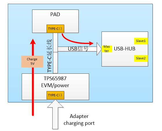
Functional block diagram:
Function description to be implemented:
1. When the adapter is not inserted, the pad can read the USB device, that is, the pad can supply power to the outside and interact with the outside.
2. When the adapter is inserted, the adapter charges the pad with 5V voltage. At the same time, the pad can exchange data through USB.
In the current test, tps65987 EVM board and 24V adapter are used for power supply
Question:
1. How to configure the tool through the application customization tool? Read the on-chip configuration file on the tooling board. How to download it from the configuration tool to the on-chip configuration file on the tooling board?
2. At present, when the evaluation board charges the pad, it will automatically negotiate the 9V fast charging mode. We don't want the fast charging mode. How to configure it?
3. After the pad and the evaluation board are connected, plug and unplug the power adapter, and it cannot automatically switch to the charging mode. Press the reset button of the EVM evaluation board to enter the charging mode.
Before reset, pad can identify USB device. After reset, when it enters fast charging mode, it cannot identify USB device. Why?


