This thread has been locked.

If you have a related question, please click the "Ask a related question" button in the top right corner. The newly created question will be automatically linked to this question.

TPS65987EVM: 5v

Part Number: TPS65987EVM
Other Parts Discussed in Thread: TPS65987, TPS65987D

If we use a 5V adapter as power supply, can we use TPS65987 to realize the following functions?

1) Charge other device through TPS65987 ,

2) At the same time, the D+ D- signal of device can be recognized, which is similar to the function of the port dock.

3)Once the adapter is removed, the device can work as source power.


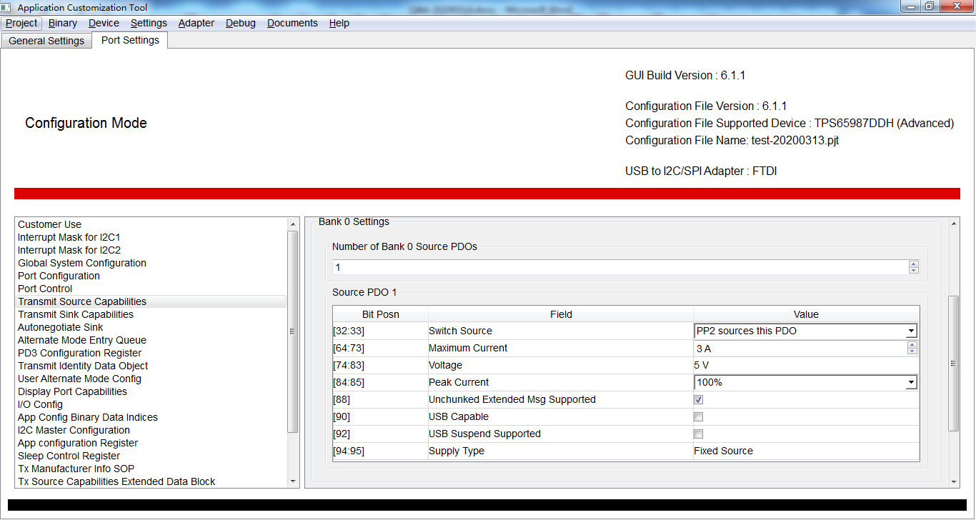
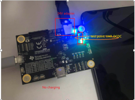
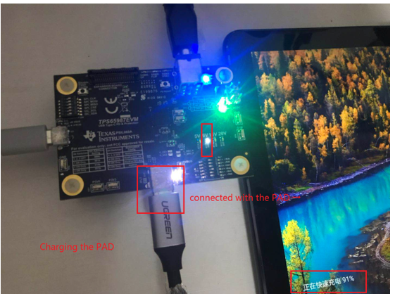
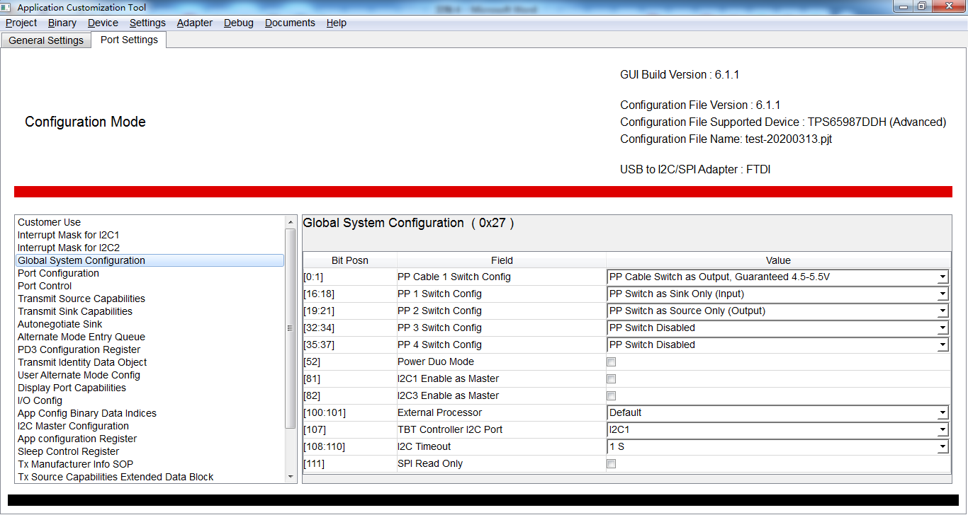
while, it seems that the TPS65987D EVM doesn't work as expected. When a 5V adapter was used to supply power for EVM, the device cannot be charged by EVM through type-c connecting. Once a 24V adapter was used, the device could be charged by EVM taht the charging power was 9V. The configuration project such as PDO has no effect.

  • Hello Zhang,

    Would you be able to help clarify your overall setup for me?

    1. Is the TPS65987DEVM acting as the source or sink in your setup?
    2. Where are you supplying the 5V and 20V adapters? Could you share the test point you are connecting to?
    3. What is your "device" and where are you connecting the device in respects to the TPS65987DEVM?

  • 1) The TPS65987 worked as source when charging the device. The configuration was as follows:


    2) As shown in the picture, we used a 24 adapter to supply power. When the PAD wasn't connected with the EVM, the test point voltage of VAR_DCDC was 5V. While once the PAD connected, the test point voltage of VAR_DCDC became 5V, and the PAD showed that it was in the fast charging mode which was not the same as expected.


    3) What we need to do is that integrate the TPS65987 circuit on the circuit board and use a 5V adapter to supply power. Can this be achieved?


  • Hello,

    I believe you had a typo in your previous post for item 2. Below I highlighted what I believe you meant to say

    • As shown in the picture, we used a 24 adapter to supply power. When the PAD wasn't connected with the EVM, the test point voltage of VAR_DCDC was 5V. While once the PAD connected, the test point voltage of VAR_DCDC became 5V 9V, and the PAD showed that it was in the fast charging mode which was not the same as expected

    If you are seeing the DCDC change from 5V to 9V once the PAD is connected to the type-C port, then this is expected behavior. The EVM has the capability of supplying 5V, 9V, 15V, and 20V by default. The TPS65987DEVM will advertise these source capabilities to anything connected to its Type-C port, which in this example is the PAD. The PAD will see these source capabilities, and request a voltage that the EVM is capable of supplying which in this case is 9V. The TPS65987DEVM will receive the request, and then change the DCDC to output 9V instead of 5V.

    If you want the TPS65987DEVM to output only 5V, then you must change the source capabilities of the EVM using the Application Configuration tool. At the bottom of the webpage are some tutorial videos that can help you get started.

    http://www.ti.com/tool/TPS6598X-CONFIG