This thread has been locked.

If you have a related question, please click the "Ask a related question" button in the top right corner. The newly created question will be automatically linked to this question.

No linking, content of FLP pulses constantly changing.

Part Number: DP83848Q-Q1
Other Parts Discussed in Thread: PROFIBUS, DP83848I

Hi, I am trying to implement 10/100 mb/s ethernet with M12 profinet connector on my board.

This is my second set of PCB's. In first set, there was problems with level shifting on the RMII signals. Now  i have working RMII and MDIO. I tested this by setting the loopback bit on at BMCR, then sent and received a frame.

PHY and all it's schematic has stay'd the same.

For some reason i can not get this to link to another device.  I tested the older version of the board too, no linking.

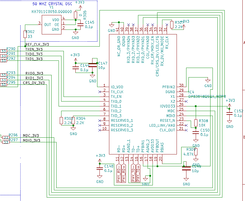
Here is the schematic for the phy:

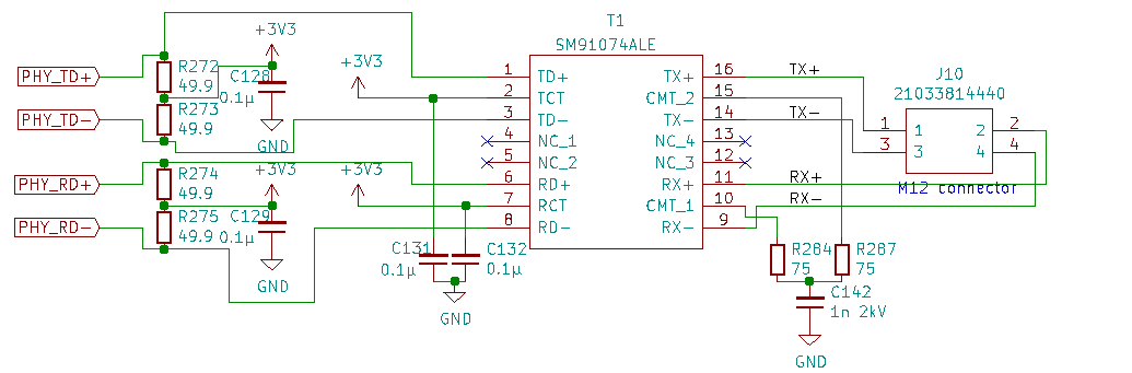
Here is the schematic for the magnetics and the connector

I have first soldered the DAP on with hot air soldering station, then connected all the pins with soldering iron under microscope. 

I soldered an LED to AN0 pin according to datasheet for debugging the linking.

This does not affect my autonegotiation strapping, since AN0 pin is set to 1 by default. In my case its unconnected.

When install jumpers from TX+ to RX+ and TX- to RX- on the M12 connector ( external loopback), and the LED turns on, indicating that link is established.

When i connect the board to my laptop with profibus cable and RJ45 crossover adapter, the link is not established. The led wont turn on, and the ethernet adapter says cable unplugged.

After disconnecting the the board from my PC, i connected oscilloscope to TX+ and TX- pins of the M12 connector on the board.

I see positive Fast Link Pulses, but it is not sending the same message constantly. Its really messy and changing constantly.

Here is an video of oscilloscope view:

I am all out of ideas where to debug. Please take a look on the schematic. i can not spot a mistake in there.

I also have one of these waveshare DP83848I modules. When i give power to this, and connect this to my laptop i get link instanty. With or without crossover adapter.

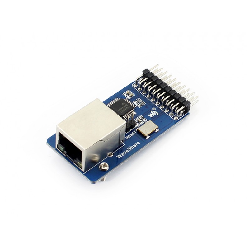
Here is a schematic for this module.

DP83848-Ethernet-Board-Schematic.pdf

I can take measurements from this, if needed.

Thank you in advance,

Jani Järvenpää

  • I measured the voltage on RBias, it was at 1.18v.

    Also measured voltage at PFBOut, voltage was 1.72v

    Measurements were done with board powered up, nothing connected to M12 connector.

    Also measured that the voltage at 3.3V power supply rail does not dip, supply does't seem to be the issue.

    Any suggestions what i could measure?

    I could post the register contents?

    -Jani

  • Hi Jani,

    Several of your image links are broken and I can't review them. Could you please send those images again? I will also need more time to review this query.

    Thanks,

    Cecilia

  • Hello Cecilia,

    Thanks for your response.

    I fixed the links on the original posting.

    -Jani

  • Hi Jani,

    Can you please first review the schematic and layout guide to ensure you have met TI's recommendations for designs with this device?

    Thanks,

    Cecilia

  • Hi,

    I reviewed the design and the recommendations and here are my thoughts:

    MDI

    The schematic is correct, and the layout is otherwise OK, but the 49.9 ohm resistors are placed near the transformer, not close to PHY.

    I am not using RJ45 connector, and the unused pairs on the cable can not be terminated thru 75 ohm resistors.


    Power supply filtering

    VDD pins have 0.1µ ceramic SMD capacitors near pads, and there is one 10µ bulk capacitor at 3.3V close to phy. No 0 ohm resitostors or ferrite beads.


    Power Feedback Supply

    This seems to be the biggest difference in my design.  I only have one 10µ ceramic capasitor and the 0.1µ capacitors are missing. I should change the 10µ cap to tantalum as recommended, and add 0.1µ caps for PFBOUT, PFBIN1 and PFBIN2


    RMII

    Series resistors in my designs RMII lines are 33 ohm, and the recommended is 50 ohm.  Traces are length matched. This is not the issue in my case, this should not affect linking.


    External oscillator

    In my design there is no pulldown resistor after series resistor.


    PCB layer stacking

    My PCB is 4 layer, and is stacked as

    -Signal

    -Ground

    -VCC

    -Signal


    Magnetics

    Transformer i have used is not in the recommended list. Good thing is that there was listed transformer that can be used with same footprint.


    I think that there is also possibility that PHY has been damaged because of the heat while reflowing the DAP. I think that i should try to replace it, and only solder the pins without using hot air. The data sheet says Die Attach Pad provides thermal dissapation.

    -Jani


  • Hi Jani,

    If you are able to replace the PHY as well, please let me know if you still run into issues. If so, we can review the items from the troubleshoot list and see if those are causing the problems as well.

    Thanks,

    Cecilia