This thread has been locked.

If you have a related question, please click the "Ask a related question" button in the top right corner. The newly created question will be automatically linked to this question.

TPS65987DDJ: 100 watt PD configuration

Part Number: TPS65987DDJ
Other Parts Discussed in Thread: TPS65987D, TPS65987

Hi,

One of my customer wants to use TPS65987D for 100 Watt PD requirement, they raised few queries related to design configuration.

They want to use this device as power PD & how to configure for 20V / 5A application?

Their preference if for auto configuration depending on source available to PD, is it possible or need software configuration to achieve the same. If software configuration is needed then their TPS65987D should be support 20V / 15V as a default input, how to configure for the same?

Pls. help with the response on above queires.

Mitesh

  • Hello Mitesh,

    I have a few clarifying questions first

    1. There will be different supplies to PPHV of the TPS65987D? Will they all be able to supply 20V?

    2. Do you have an EC available on the system that can connect to a TPS65987D GPIO?

    3. Will the TPS65987D be acting as the Source or Sink for the 100W?

  • Hi Adam,

    Pls. find below response.

    1.    There will be different supplies to PPHV of the TPS65987D? Will they all be able to supply 20V?

    - Application is to derive the power from USB Type C connector at 20V/5A source connected at connector. There will be only one supply input from VBUS input.

    2. Do you have an EC available on the system that can connect to a TPS65987D GPIO?

    - There will be EC available to connect the I2C lines of TPS65987D, if configuration is required.

    3. Will the TPS65987D be acting as the Source or Sink for the 100W?

    - TPS65987D in our application would act to Sink 100W from TYPE C Power Source.

    Mitesh

  • Hello Mitesh,

    Thank you for the clarification. Since you want the PD controller to sink the 100W of power, this should be pretty straight forward.

    First, you will need to download the Application Configuration tool used to program the TPS65987D, which can be found using the following link. There are some tutorial videos at the bottom of the page to help you get started.

    http://www.ti.com/tool/TPS6598X-CONFIG

    Next, you will change the sink capabilities register to advertise that the PD controller can sink up to 20V/5A, but can also support 20V/3A and 15V depending on the type of adapter attached. The PD controller will automatically select the highest power option available based on the sink capabilities you have programmed.

    One thing to note though is that a 5A contract is also dependent on the cable. Meaning that during the power negotiation sequence, one step is that the source PD controller communicates with the cable to see what it can handle. If it receives a response o 3A or no response at all, then the source PD controller will not provide the 100W of power even if it capable of that. Just one thing to note as you continue evaluating your system.

  • Hi Adam,

    Kindly find schematic for review from customer.

    Queries from customer

    • On this board there is no other power source available, only source will be USB TYPE C, so how to program the TPS65987 if EC itself is not powered, how to setup for 100 watt?
    • Is there any sequence of command requirement for default 20V/5A (100 Watt) PD configuration?
    • What are the register needs to modify?
    • Is there any software script available for register writing? 
    • kept provision for memory, will it good enough for initial startup & configuration?
    • How to power up the memory in that case, will it need one more LDO on PD bus to provide power to memory?

    Mitesh

    USB_PD for TI review.pdf

  • Adam,

    Pls. help with your comments & also need review comments.

    Mitesh

  • Answers to your above questions.

    • On this board there is no other power source available, only source will be USB TYPE C, so how to program the TPS65987 if EC itself is not powered, how to setup for 100 watt?

    You can use an external SPI flash that is powered from an LDO on the PD controller. Whenever the PD controller boots from VBUS, it will power the SPI flash, ad load the configuration. You can refer to the TPS65987DEVM for reference.

    • Is there any sequence of command requirement for default 20V/5A (100 Watt) PD configuration?

    You must change the sink capabilities register within the TPS65987D using the application configuration shared above

    • What are the register needs to modify?

    Register 0x33 is the sink capabilities register

    • Is there any software script available for register writing? 

    In some of the app notes there are code snippets but in general no, there is no default code repository for I2C master communication

    • kept provision for memory, will it good enough for initial startup & configuration?

    Not sure I understand this question

    • How to power up the memory in that case, will it need one more LDO on PD bus to provide power to memory?

    Use LDO_3V3 from the PD controller to boot the SPI flash as well as all relevant pull up resistors. Refer to the TPS65987DEVM

  • Hi Adam,

    Can you also help with schematic review?

    On one of the query you mentioned " Not sure I understand this question"--> for this query is " in this case only power source available to board is PD source, so processor will also not in powered condition when user will connect PD source. In this condition we believe Memory should load the configuration with the help of internal LDO available" , is it correct assumption? because initially processor will also not in powered up condition that means no active I2C communication available for PD device configuration. Memory must configure the TPS65987 upfront.

    Mitesh

  • Hello Mitesh,

    Yes, you may email me the schematic for review.

    For the other question, yes your understanding is correct. If you use an external SPI flash to load the application configuration onto the PD controller, then there will be no problem in the scenario you outlined. If power is only asserted on VBUS, the PD controller will power itself from VBUS, power the external SPI flash from LDO_3V3, and load the configuration that you have already programmed to the flash. Once the configuration is loaded, the TPS65987D will negotiate a high voltage contract and power the rest of your system

  • Hi Adam,

    Schematic already attached in earlier post.

    Mitesh

  • Hello Mitesh,

    Only thing from the schematic is that you can only have a maximum of 10uF on VBUS on the connector side. You must DNP the 47uF capacitor connected to the Type-C connector if you wish to by compliant

  • Hi Adam,

    Customer system requirement is of 100W power support from PD controller with internal FETs only.  

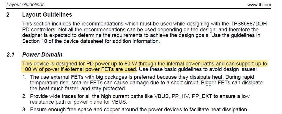
    However "USB_PD_HW design guidelines document (SLVA888B)" mentions that internal FETs can support only 60W power. Please refer below snapshot for the same,

    So, is this correct? Does internal FETs can't support 100W power? Do they need to use external FETs? 

    Please confirm the same ASAP.

    Mitesh

  • Hi Adam,

    Their system requirement is of 100W power support from PD controller with internal FETs only.  

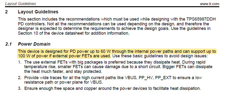
    However "USB_PD_HW design guidelines document (SLVA888B)" mentions that internal FETs can support only 60W power. Please refer below snapshot for the same,


    So, is this correct? Does internal FETs can't support 100W power? Do they need to use external FETs? 

    Please confirm the same ASAP.

    Mitesh

  • Hello Mitesh,

    You can use the internal FETs for a 100W system, but they were designed for 60W applications. With that much power, in the event of a short circuit, the FETs could be damaged due to temperature rise of the die. This section is just advocating these concerns for power design.

    If this system is a sink only application, you could implement the power duo functionality which closes both internal power paths at the same time, allowing you to use both power paths in parallel. This reduces the amount of current going through one path at a time and can withstand the 100W system