This thread has been locked.

If you have a related question, please click the "Ask a related question" button in the top right corner. The newly created question will be automatically linked to this question.

DS90UB925Q-Q1: How does the default pull-down resistor (G1 pin) work in DS90UB925 power-up and power-down situations, and how much impedance it presents

Part Number: DS90UB925Q-Q1

Hi Team,

One input pin of DS90UB925 (G1) multiplexes the startup configuration of CPU. The CPU must detect a high level to enter the configured mode to start when power is turned on.

Now G1  pin of DS90UB925 defaults to pull down to cause startup failure.

I want to know How does the default pull-down resistor work in DS90UB925 power-up and power-down situations, and how much impedance it presents.  Because the amplitude of the partial voltage change obtained by adjusting the resistance of pull-up resistor R182 is small.

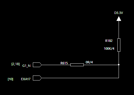
As shown in the EXA17 network below, the voltage of EXA17 is 2.11V due to the default pull-down in DS90UB925, which is not enough to start the SOC.

  • Hello Amelie,

    To clarify you are using the G1 pin to enable the SoC?  Are the values of the resistors shown fixed or can they be changed?  The pull down on these pins is pretty weak and very well could drop enough voltage to affect EXA17.

    Regards,

    Nick

  • Hi Nick,

    As G1 in 925 could also be used as GPIO3, customer now use G1 as GPIO3 to control. As you could see in the above picrue,GPIO3 is reused with EXA17, which is the startup of MCU.

    Because the default value of GPIO3/G1 is  pull-down.When customer use R182=100k/4, which lead to Voltage of EXA17 is only 2.11V.

    Could you please share the internal circuit of G1/GPIO3 (actually just pull-down res is ok)?

  • Hi Amelie,

    The internal pull-down resistor is in the order of 300kOhms.  Which matches up with the voltage you are seeing at EXA17.

    What is the minimum voltage the MCU needs to see in order to startup properly?

    Regards,

    Nick