This thread has been locked.

If you have a related question, please click the "Ask a related question" button in the top right corner. The newly created question will be automatically linked to this question.

DS90UB914A-Q1: Enable GPIO local operation

Part Number: DS90UB914A-Q1

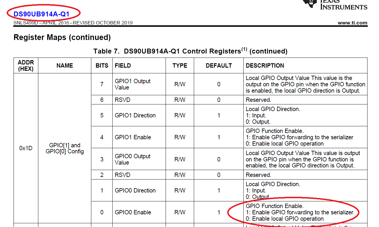
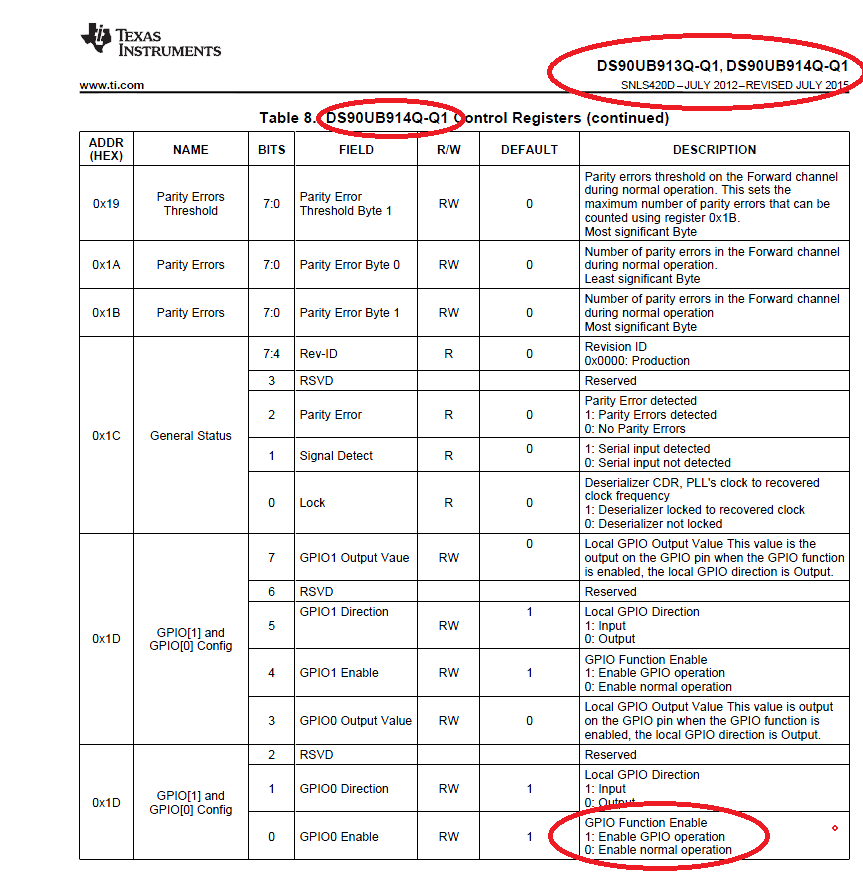
Hello, a user reported he is getting an incorrect response on the setting of the address 0x1D, bit 0 (GPIO0 Enable). Can we please request for your help to very it? Below are the details provided by the user:

"In order to directly control the GPIO trough I2C i had to put a 1 into this field. This applies for all GPIO's.

I have an FPGA connected to the DS90UB914A-Q1. For test purposes i want to toggle GPIO0 on the DS90UB914A-Q1 via I2C commands from the FPGA. The DS90UB913A-Q1 is not yet involved at this stage.

When i set 1x1D bit 0 to 0 i can not control the GPIO0 via I2C. Only when i set this bit to 1. In Order to toggle GPIO0 i have to write

writei2cDESER(0x1D,0b00000001);    // GPIO0 low

and

writei2cDESER(0x1D,0b00001001); // GPIO high"

Thank you!

  • Hello Elisha,

    Are you talking about register 0x0D? 0x1D is the wrong register for controlling GPIO0. 

    Also this behavior is as expected. 0x0D[0] controls whether the GPIO is an input or an output. 0x0D[3] controls the logic state 0/1 if the GPIO is assigned as an output. You can see this in the datasheet. 

    Best Regards,

    Casey 

  • Hi Casey

    Thanks a lot for your response. Probably you had a look on the DS90UB913 datasheet, but i'm talking about the DS90UB914 (please see the message above).

    I will include a screenshot of the datasheet:

    and here from another datasheet (DS90UB913 and DS90UB914 combinded):

    In order to control the GPIO with an I2C master (local operation), i made the expirience that this bit must bi set to 1, in contrary to what i would interprete when reading the first datasheet. It is a bit more clear in the second datasheet.

    Thanks a lot!

    Christian