This thread has been locked.

If you have a related question, please click the "Ask a related question" button in the top right corner. The newly created question will be automatically linked to this question.

TMDS181: S-parameters

Part Number: TMDS181

Hi, 

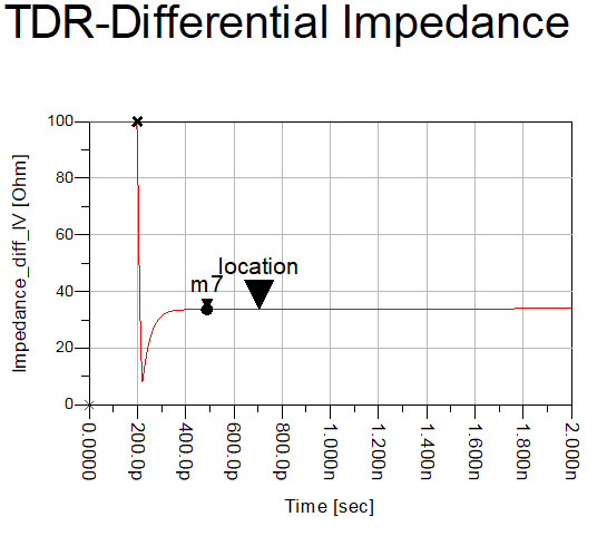
I'm trying to simulate the effects of the TMDS181 package on the HDMI transmission line.

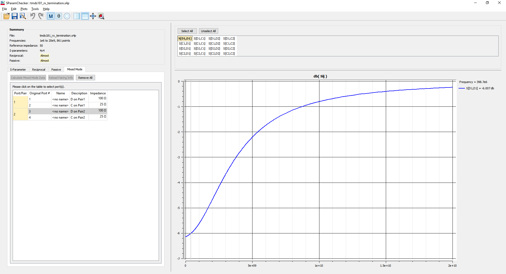
I'm primarily interested in the receiver so I'm using the 'tmds181_rx_termination.s4p' file. Can you confirm the input/output port mapping as this isn't clear to me from either the guide or s-parameter comments. 

Thanks

  • HI

    Port 1 (+) and 3 (-) are the input, and 2 (+) and 4(-) are the output.

    Thanks

    David

  • Hi David,

    Thanks for your reply.

    I'm still having trouble with this model - could someone contact me offline to discuss this further?

    Many thanks

  • There is an archived ADS workspace: TMDS181_RELEASE_ADS.7zads, have you tried to un-archive it and use it as the baseline for the simulation?

    What is the issue you have with the model?

    Thanks

    David

  • Hi David, 

    I was getting some very strange results with the port mapping you suggested but looking at the workspace, it looks like 1/2 is input and 3/4 is output - hopefully I've interpreted this correctly. 

    Upon viewing the s-parameter results using 1/2 as input and 3/4 as output I see a very poor return loss (-6dB @ near 0Hz) and the insertion loss doesn't appear to start from 0 which I've not seen before. I'm fairly new to interpreting s-parameters so it's quite possible that I've got the mixed-mode conversion wrong or am missing something but it would be great if you could clarify. I've attached images below. 

    Further to this, running a quick TDR test on the model - I see the following below. It seems to stray very far from the nominal 100Ohm impedance required. I assume I'm over-terminated somewhere but it would be great if you could advise. My schematic is essentially a TDR source connected directly to 1/2 of the tmds181_rx_termination.s4p model and then a 100R terminator across ports 3/4. There is nothing else in the circuit.

    Many thanks

  • What are you trying to simulate? Are you trying to see if the TMDS181_rx_termination.s4p model has a 100ohm differential impedance? 

    The model is intend to be used with other TMDS181 model components to mimic a complete TMDS181 retimer response, it is not intend to be used separately. 

    Thanks

    David

  • Hi David, 

    I need to simulate the effect the TMDS181 has on the impedance of a transmission line. I am trying to run a TDR test of the whole transmission line to do this but every time I include the TMDS181_rx_termination.s4p model the results look a little odd as if there's something wrong with the model. 

    Can you advise how best to achieve what I'm trying to do? Do you have a model which represents the bond wire and any other loading the receiver might apply to the channel?

    Thanks

  • Unfortunately I don't have a model that represents just the package, the bond wire, and other loading of the TMDS181 RX. The  TMDS181_rx_termination.s4p model was never set up as a way to test the TDR of a transmission line.

    Thanks

    David