This thread has been locked.

If you have a related question, please click the "Ask a related question" button in the top right corner. The newly created question will be automatically linked to this question.

PCA9517: A question about a spike on B side SDA of PCA9517

Part Number: PCA9517
Other Parts Discussed in Thread: TCA9517

Hi,

When my customer is using PCA9517, they are facing a question.

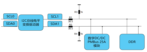
here is their block diagram:

"I2C总线电平变换驱动器" is PCA9517.

"数字DC/DC PMBUS 25A模块"  is a DC/DC power module with PMbus.

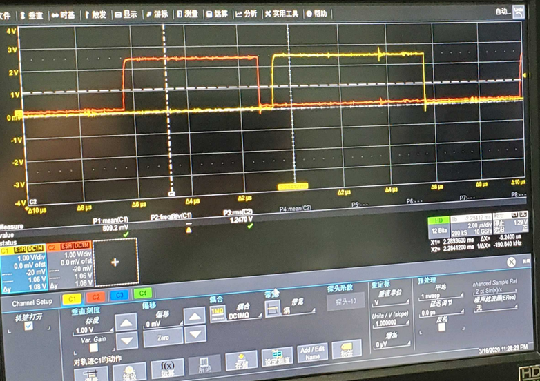
here is the input waveform:

the yellow one is SDA0, the red one is SCL0.

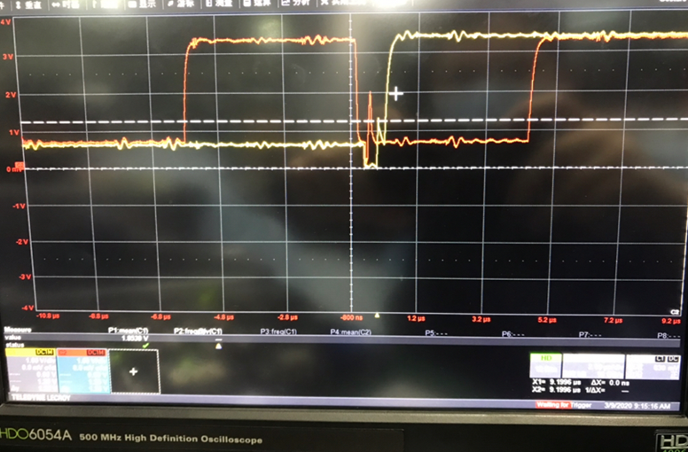
but we find a spike on SCL output,

the yellow one is SDA1, the red one is SCL1.

After we remove R1 and R2, the spike disappeared.

Our question is: why there is a spike on SCL on B side? ow to avoid it?

Thank you.

Best Regards

  • Hi Erwin,

    This device has a known errata on the B-side where the device may cause an overshoot during certain events such as clock-stretching. The series resistances are likely exaggerating this phenomenon by presenting an apparent load to the pin, delaying its response. For this reason we recommend the use of TCA9517 for new designs. For designs using PCA9517, it is recommended that rise-time-accelerators are not used on the B-side of the device or including a large capacitive load to the bus to limit the overshoot. For more information, please see the errata description in Section 8.2.1 of PCA9517's datasheet. 

    If you believe there may be something else causing the issue, please let me know. 

    Regards,
    Eric

  • hi, Eric,

    Thanks for your reply, i have read 8.2.1, but in the figure, the spike was on SDA, not SCL. the spike on SCL and SDA have the same reason?

    If we can't add a capacitive load, can we change the pull-up resistor value to 10K to limit the current?

    Thank you

    Best Regards

    Erwin

  • Hi Erwin,

    I believe both lines (SDA vs SCL) use the same circuitry so the same phenomenon can occur on either line. It is most prevalent in SCL during clock stretching because of the nature of how this occurs (small variations in low-level outputs occuring closely together). 

    This spike is often caused by a rise-time accelerator being mis-triggered. Because this type of signal rise is not related to the pull-up resistor, changing this value would likely not dampen the spike directly. Increasing the size of this resistor may allow for other devices to pull a lower low-level voltage which could keep any rise-time accelerators from triggering, however it will not have much impact on the static voltage offset of PCA9517. 

    Is it possible to change the device you are using to TCA9517? This device is an exact equivalent to PCA9517 but includes a solution to this errata.

    Regards,
    Eric