This thread has been locked.

If you have a related question, please click the "Ask a related question" button in the top right corner. The newly created question will be automatically linked to this question.

TCA8418: TCA8418 pull-down signal cannot be detected

Part Number: TCA8418


Hi,

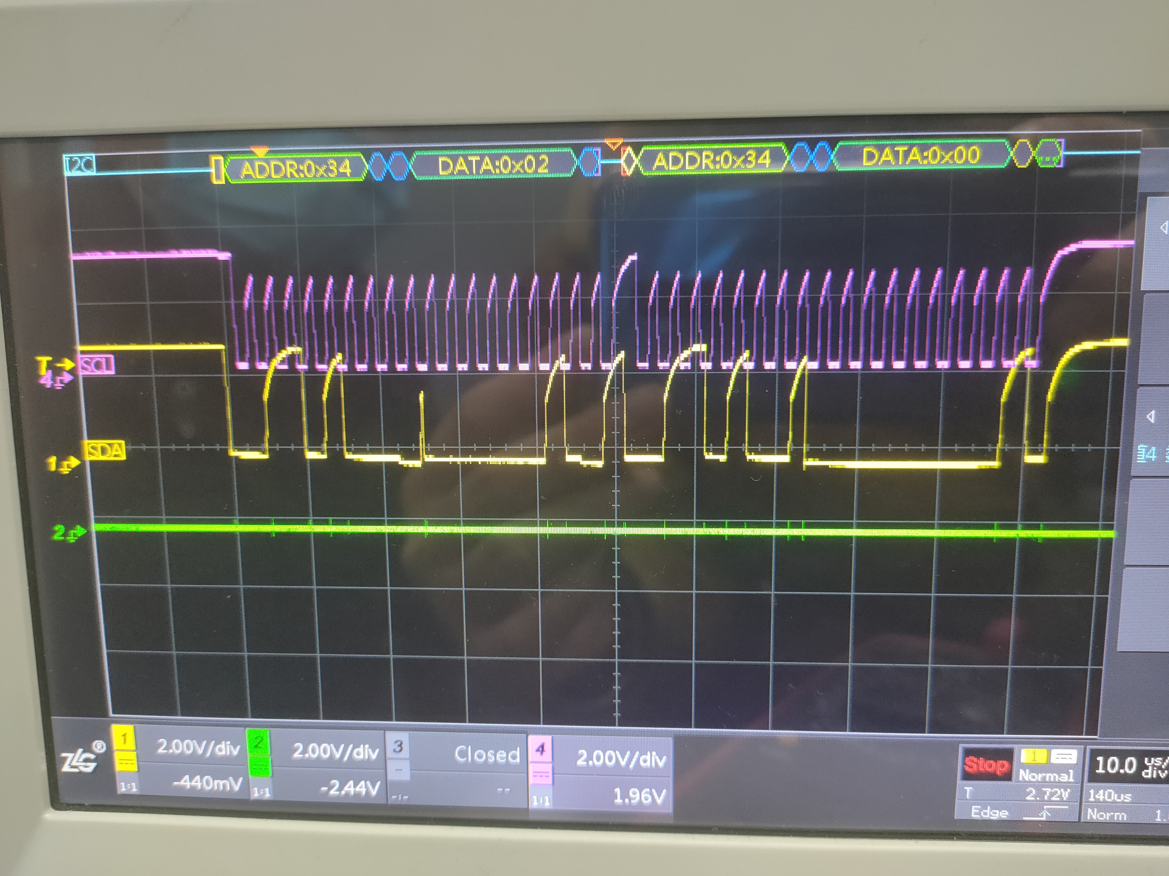
 I2C can operate the register now, but the pull-down signal cannot be detected when the key is pressed once. Theoretically, there should be a pull-down. What is the possible reason?

Does the different KPCOL have to be pulled externally, or is the register configured high? Does the different KROW only affect him? Which register Settings affect him?

Thanks!

  • Hi Neal,

    For how long is the key pressed? Can you verify the voltage while the key is depressed vs. when it is inactive so that we can verify there are no hardware issues?

    In terms of the software/firmware, how are you detecting when a key is pressed? I.e., which registers are you reading?

    Regards,

    Max

  • Neal,

    Can you provide a schematic?

    Can you also provide register values of how the device was configured?

    "Does the different KPCOL have to be pulled externally, or is the register configured high?"

    If the column is set to be in keypad mode, then it is either HI-Z (scan mode where it will strobe to Hi-Z) or GND depending on the mode (active scan or idle).

    "Does the different KROW only affect him?"

    The row is an input when in keypad mode which is pulled high by a 100k pull up resistor.

    "Which register Settings affect him?"

    0x1D-0x1F sets the KP mode or GPIO. At power up, the device is a GPIO all pulled high internally with a 100k pull up.

    -Bobby

  • Hi,

    We have found the reason for this problem, it is the PCB Layout,

    Now there's another problem,

    If the key is not pressed, the normal high and low level of register 02 is detected. When the key is pressed, the low potential is detected,

    What could be the reason?

    Thanks!

  • Hey Neal,

    Did you add additional capacitance to any rows or columns?

    "If the key is not pressed, the normal high and low level of register 02 is detected. When the key is pressed, the low potential is detected,"

    Can you provide a scopeshot for the keypad press on the row you are seeing a detection? I'm not exactly sure what you are trying to describe here.

    Thanks,

    -Bobby

  • Hi,

    Let me redescribe the problem.

    At present, our chip can normally write the value of the register, and the signal of the measurement level does take effect, but it cannot be read properly.

    We have configured the slave address to be 0x34, register 0x01 to be set to 0x19, configure 0x1d,0x1e,0x1f to be KP matrix,

    when we press the key, interrupt is low to read the status register 0x02 value, is always 0. Read 0x04 register is always 0x80. We measured the waveform

    of i2c, as shown in the attachment, the slave machine did feedback 0, I want to ask why the key was pressed, the interrupt was triggered, but the register

    value read is wrong.Do i need configure any other registers for the chip to work properly.

    Thanks !

  • Your waveform shows your I2C bus is struggling to keep up with the clock frequency you currently have set. You can see that the clock high periods never get close to Vcc and I would argue you may not even be reaching 70% of Vcc. I think you are violating the I2C rise times right now which could be causing signal integrity problems.

    I would reccommend changing your pull up resistors on SDA/SCL to atleast half of what the current value or or even more. For reference I2C rise times at 400kHz need to be 300ns measured from 30% of Vcc to 70%.

    I recommend you do an I2C write and then do an I2C read immediately after each register write to ensure you are actually writing to the register you think you are.

    Try to first set register 0x01h to 0x81h

    Immediately read to see if 0x01h is set to 0x81h <-- AI enable, Key Events generate INT

    then go to register 0x03h and write 0x00h <-- we want to ensure the keypad lock is not enabled

    Read 0x03h register to ensure that bit 7 is set to 0

    Next write to register 0x1Dh data: 0xFFh, 0xFFh, 0x03h [do this all in one transaction]

    This should enable registers 0x1D-0x1F to be part of the keypad matrix (remember we set the auto increment in register 0x01h to be set)

    Read the register and read all 3 bytes before issuing a stop condition and ensure that you get 0xFFh, 0xFFh, 0x03h

    Now press a key (or GND any of the rows)

    This should generate an interrupt (INT should now go from high to low)

    read register 0x03h, you should see it say 0x01h indicating that 1 event has occured  if you GNDed the row if you pressed and released the button then you should see 2 events represented as 0x02h instead.

    Now read register 0x04h, this should tell you which row/col was driven low.

    If you are still having issues after following these instructions then can you upload the write  and read sequence of
    "Try to first set register 0x01h to 0x81h then Immediately read to see if 0x01h is set to 0x81h"

    ^(o-scope shot of this transaction)^

    We can debug this step by step

    Thanks,

    -Bobby

  • HI

    Thank you for the debug Suggestions you gave us before. We have solved this problem, and we can work normally with a new i2c. Before that, it was because our SDA signal of i2c could not succeed when reading the data, but other devices on the i2c were working normally. We have modified the stability of i2c and confirmed the specific cause of the problem before. Anyway, thanks for your advice.

    Thanks

  • Hi

    Recently, we have a new problem. I want to ask you a question. When we quickly slide a row of keys, we will lose a lot of key values. At that time, there is no signal in the interruption. Is this because a scan needs 20ms, and our interval time is less than 20ms? If so, can we optimize it? If not, what configuration do we need to modify?

    Thanks.

  • Hello,

    Sorry I didn't see you replied and reopened this thread until just now.

    To verify, you are able to read key presses normally when you press one key at a time?

    When you press multiple keys quickly, what does register 0x03h read?

    "Is this because a scan needs 20ms, and our interval time is less than 20ms?"

    The scan takes 25 milliseconds however it requires 2 scans in order to actually confirm a button press (this is a built in check for the device). The worst case is if you press the button immediately after the col has been scanned. This would mean you are required to keep the button pressed 50ms before the button is recognized as pressed. The minimum time is if you press the button immediately before the col is scanned, then you would need to only wait about 25 milliseconds to recognize the button press. If you quick press is less than 50ms then you could miss the press though realistically this is difficult for a human to type (press and release) this fast.

    "When we quickly slide a row of keys, we will lose a lot of key values"

    The FIFO stores 10 events or 5 keys pressed (one for press and one for release). If you are not reading the FIFO fast enough then you will overflow.

    -Bobby

  • Hi

    No problem, thank you for your reply.

    When I press only one key at a time, I can get the normal key value. There is no problem in normal use.

    When I quickly press multiple keys, register 0x03h reads a maximum value of 10.We will not do the test for multiple keys.Because our products rarely use this feature.


    When I quickly slide the key, I will lose the key without interruption. The value read in 0x03 register is 1. In fact, it is only a single key press, but the interval time is very short. Therefore, it is doubted that the internal scanning time is longer than the interval time of the key press. Because we test the fast slide, and there are 10 keys slide, and the scanning time is 50ms, then There must be a key missing.

    If the internal scanning specification of the device is 50ms, then we can't optimize this problem, right?Because we can confirm that the interval time is less than 50ms.

    Thanks.

  • "When I quickly slide the key, I will lose the key without interruption. The value read in 0x03 register is 1. In fact, it is only a single key press, but the interval time is very short. Therefore, it is doubted that the internal scanning time is longer than the interval time of the key press. Because we test the fast slide, and there are 10 keys slide, and the scanning time is 50ms, then There must be a key missing.

    If the internal scanning specification of the device is 50ms, then we can't optimize this problem, right?Because we can confirm that the interval time is less than 50ms."

    You should still see an INT if there is still data in the FIFO. The INT would be held asserted to LOW until the FIFO is cleared. There is an option to make the INT de-assert momentarily(it will make the INT toggle) in register 0x01h by setting bit 4 to = 0. Please also confirm that register 0x01h bit 0 is set to '1'

    You may also want to check section 8.1.4 of the datasheet involving the overflow errata if you are using the non-E version of TCA8418.

    -Bobby