This thread has been locked.

If you have a related question, please click the "Ask a related question" button in the top right corner. The newly created question will be automatically linked to this question.

TUSB217-Q1: Improve Signal Quality Margin for 4m USB 2.0 High Speed Cable with TUSB217

Part Number: TUSB217-Q1
Other Parts Discussed in Thread: TUSB217, TUSB216

We have a USB 2.0 Device to Device communication link that has been experiencing signal quality problems. Our setup is shown below.

Board A has a USB 2.0 Hub. In the first configuration the communication link goes from Board A through a connector to Board B then to the cable and on to Board C and D where there is another Hub. Cable lengths vary from 0.5m to 3m. Note that all cables are detachable on both ends.

In the second configuration, the cable also has a Board E in the middle with another USB 2.0 Hub. In this case each side of the cable is 4m for a total of 8m with hub in the middle.

We have experienced signal quality issues particularly with the longer 8m cable.

Shown below are far end USB 2.0 eye diagrams for the USB 2.0 High Speed signals at Board A, Board E, and Board D with the 8m cable. These eye diagrams were measured at the Hub pins. The 5th eye diagram shows a cable that was by far worse than most we have seen but does represent an exceptionally bad signal quality situation.

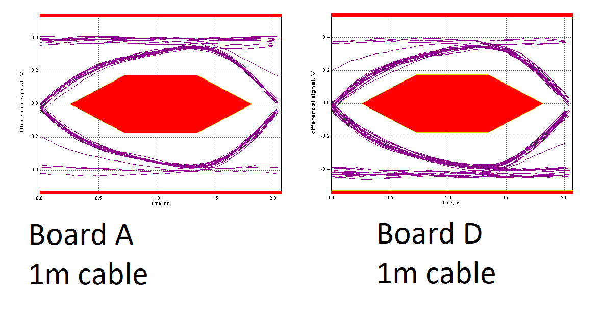
Here is what the far end eye diagrams look like with 1m cable.

If we were to use the TUSB217 to open up the eye diagrams where would you recommend we put them? Do you think we could boost the worst eye diagram shown while still staying within compliance for the shorter cable lengths? 

Thank you,

Ethan

  • Hi Ethan,

    Could you retry posting your images some of them have not uploaded correctly. Also if you have a block diagram of your setup it would help me understand the testing you are doing and your application. In general we recommend placing TUSB217 closest to your connector or ~4-5 m away from your USB Host or Hub (depending on the quality of the cable). Placing TUSB217 such that the length is split by half on each side can also work. 

  • Hello Malik,

    Thank you for the reply. Here is the first image, showing the setup of our system. 

    Here is the second image, showing far end eye diagrams for the various points in the system using the 8m cable. The final eye diagram shows a worse than normal cable. 

  • Hi Ethan,

    It seems that you need two TUSB217 for the application as there is a large amount of loss through Boards B and C. Do the USB Hubs you are using have the ability to increase drive strength of there USB 2 Phy? That may also help here.

    The other cable seems to have a issue that there is a large DC imbalance between DP and DM causing the Eye to be shifted down, in addition to large amounts of loss. Do you have SE DP and DM waveforms for this case?

  • Hi Malik,

    Thank you for your response.  Where would you recommend placing the 2x TUSB217 in this case? I agree we have large loss through boards B and C, I think this is largely due to the connectors not being true 90ohm differential connectors. We are using the USB2517 and USB2512b hubs from Microchip and have already increased the drive strength to +12% on each port.

    I do not have single-ended waveforms for the last eye diagram. I see what you mean that the whole eye is shifted down. It is also has a lot of attenuation in the differential peak-to-peak measurement. We think some of the variation we are seeing in the cables may be due to having a braid shield only instead of foil + braid over the twisted pair. Is this something you could confirm may impact the signal quality/attenuation? Our theory is that the braid shield coverage could be variable from cable to cable and the signal quality suffers accordingly. 

    If we placed a TUSB217 on Board B and Board C, do you think the eye diagrams would open up significantly at Board E in the middle of the cable?

    Thank you,

    Ethan

  • Hi Ethan,

    I think placing both closest to board B and board C could definitely help the signal integrity and potentially open the eye a bit. I will recommend you look into TUSB216 and the associated EVM. TUSB216 is our latest USB 2 redriver and has more re-driving capability than TUSB216. i would also ensure that the Hubs themseleves pass a near end eye mask test as well (measured directly at the connector).

    The shielding of the cable will definitely play a role in the signal integrity of the cable. For example un-shielded cables will perform once than shielded cables. I cannot comment specifically on the types of shielding you are using but it does seem to have an impact. The gauge of the cable also has been shown to effect the frequency response of the cable. 

  • Hello Malik,

    Thank you. I purchased the TUSB217 EVM and will see how that helps. It appears the TUSB216 and TUSB217 are the same device in different packages?

    Thank you for your comments on the cable. We are working with our cable manufacturer on changing the shield to add the foil + braid. I thought it was worth asking as you probably deal with high speed signal quality details regularly and I am not a cable expert. 

    Thank you very much for your assistance. I will follow up this post if I have more questions after my testing with the TUSB217 EVM.

    Thank you,

    Ethan

  • Hi Ethan,

    No, TUSB216 is our most recent generation of USB 2 redrivers and has more drive capability than TUSB217.