This thread has been locked.

If you have a related question, please click the "Ask a related question" button in the top right corner. The newly created question will be automatically linked to this question.

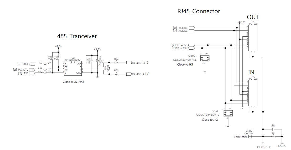
SN65HVD08: Review circuits, using 485 transceiver and improve ESD.

Part Number: SN65HVD08
Other Parts Discussed in Thread: THVD1429, THVD1450, , STRIKE

Dear TI and all,

Above circuit is part of connecting audio device.       

JK1, JK2 is RJ45 JACK(refer to attached a file PCB-832(RJ45 Jack).pdf.)


This jack is used to connect audio devices.(For DC power , 485 comm. and audio signal)

I have a question below this.

To suppress ESD of Power and signals, I added Q109, Q23.

There circuit need to add another parts improve ESD or another electrical characterisctics? 

Please, review that circuits.

Best Regards,

Inho Jeon

PS.

I don't understand that body of RJ45 Jack connected chassis ground and analog ground(refer above circuits). Is it right way?  

I think that way is improved ESD, EMC. Is that right?

Please, inform me solution of my questions.   


  • Hello,

    Use of an SM712 diode should be effective at suppressing most ESD events that could be expected at a standard RS-485 interface.  Alternatively, you could consider using an RS-485 transceiver with higher levels of internal protection.  Some p2p examples are THVD1450 or THVD1429.

    On your RS-485 implementation, I'd recommend a pull-up resistance on the "R" output.  This pin is high-Z when the /RE line is high, so an external pull-up is useful for ensuring that the MCU/UART being used receives a valid logic "high" level while it is transmitting messages.

    The RC network connecting chassis ground to an internal ground is useful in quickly discharging fast surges present on the internal ground (via capacitance) and preventing the longer-term buildup of charge between the grounds (so that the potential difference between these is kept minimal).  I'm not sure in your system if it would make more sense to connect this RC network to the ground used by the transceiver (which is more typical) rather than an analog ground.

    Max

  • Dear Max,

    Thank you for reply.

    "THVD1450 and THVD1429", Is that compatible to SN65HVD08 ?

    On your reply, 'RS-485 pull-up resistor on the "R" output' is like to U3.1 on my circuits, Is it right?

    And, 'quickly discharging fast surges' is like suppress ESD, is it right?

    Thank you.

    Best Regards,

    Inho Jeon

  • Yes, both devices are compatible with HVD08.

    In your circuit it looks like there is a 4.7-kOhm pull-up on D (U3 pin 4).  The same circuit is recommended on R (U3 pin 1).

    Yes, by fast surges I meant coupled transient noise like ESD.

    Best regards,
    Max

  • Dear Max,

    Thank you for reply.

    And, I have a question about my circuits.

    On my circuit Q109, Q23  connected 'digital Ground'. Is that right?

    ('digital ground' is for  power and digital signal.  

     AND is for  audio signal.

    CHGND is for chassis ground.)


    If it is not right, Recommend right way, please. 

    Thank you.

    Best Regards,

    Inho Jeon

  • Yes, I believe it makes sense to reference these components to a "digital" ground so that the "analog" ground will not have additional noise coupled onto it (for example, when the TVS diodes clamp in an ESD strike and conduct current to the ground).

    Is there a reason that you do not have an RC connection (like C42/R51) between the digital ground and the chassis ground as well?  I think that may be beneficial in preventing ground offsets between the chassis and digital grounds.

    Max

  • Dear Max,

    Thank you for reply.

    I comment my circuits below this; 

    AGND is for audio ground.

    JK1 and JK2 is connected for 485 & audio signal. 

    Pin No. 9/10 is chassis of JK1/JK2. 

    So, I connect AGND and CHGND_2 with RC network.

    On my circuit, AGND and DGND(that is for 485 signal) is connected just 0ohm resistors.

    You means DGND and AGND need to RC network like AGND & CHGND_2, Is it right? 

    And, I have a question : I want to know difference of  THVD1450THVD1429,  SN65HVD08

    Thank you

    Best Regards,

    Inho Jeon

  • Hello,

    Since AGND and DGND are already connected I don't think you would need an additional RC network.  So, you can ignore that latest comment from me.  Thank you for clarifying.

    The SN65HVD08 was developed in 2002 as an RS-485-compliant transceiver supporting operation at both VCC = 3.3 V and VCC = 5 V.  THVD1450 is a more recent device for the same application.  Since it was developed many years later, though, it is able to incorporate a number of performance improvements.  Most notably, it integrates IEC 61000-4-2 ESD protection, wider voltage ranges (both absolute maximum and operating) on the A/B lines, and a wider temperature range.  THVD1429 was based on the THVD1450 design but also integrates an additional protection diode within the package in order to protect against even higher-energy transients such as IEC 61000-4-5 surge.

    Regards,
    Max