This thread has been locked.

If you have a related question, please click the "Ask a related question" button in the top right corner. The newly created question will be automatically linked to this question.

THVD1520: Intermittent/marginal issue with RS485 communication

Part Number: THVD1520

Hi, we are interfacing to a third party sensor and are having intermittent problems with communications.

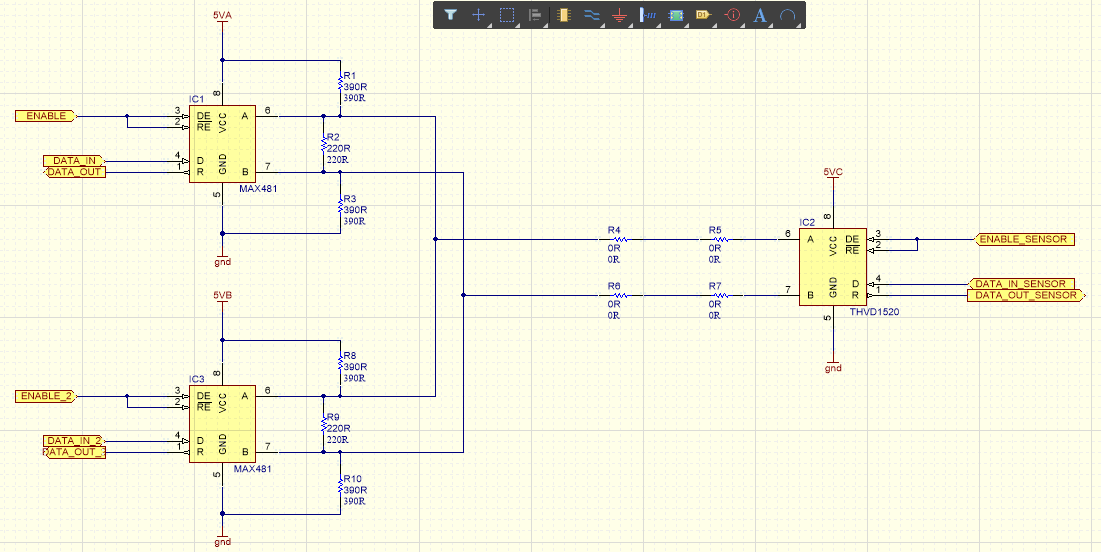
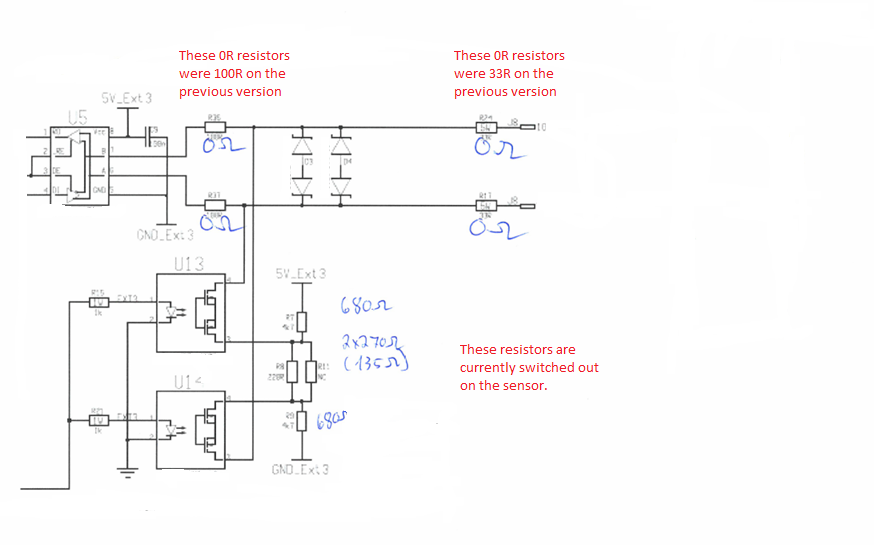
The sensor is using THVD1520 as the RS485 transceiver, we are using a Maxim device on our end.  This sensor previously worked but the manufacturer has updated it's revision and approximately 50% of the sensors we try have the same communication problem.  It appears to be a marginal problem.

We are trying to figure out what could be happening, unfortunately we have one of their sensors but aren’t able to open it to probe the circuit.

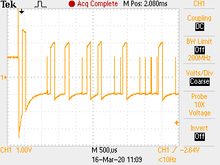
I’ve attached a screenshot that some of our guys have recorded.  It looks like for a run of zeros the transceiver briefly reverts to the idle state.  We are thinking that either the transceiver isn’t able to drive for the full length of the data or possibly the data enable line is fluctuating?

We are able to to identify our transmission and the response from the sensor; this is definitely the sensor response.

From the brief part of the circuit that we've seen /RE and DE are tied together in the sensor.

This appears to be a marginal condition, some sensors, of the same type, work and others don’t.

Is this something that has been seen before?  Can you give us any suggestions on what could be happening?

Thanks & regards,

Amanda

  • Hi Amanda,

    This looks strange and I'm not immediately sure what could be the problem.  To make sure I understand the waveform, though - is this the differential signal on the bus (VA - VB)?  And, is the ~1.1-V level at the beginning capture showing the idle-state voltage (biased, I assume, via external pull-up and pull-down resistances)?

    How is termination implemented?  Is it in your system, in the sensor, in both, nowhere, etc.?  What resistance values are used?  I ask because one thing that might create these waveforms would be if the sensor had to drive a high load current (e.g., due to low load resistance).  The sharp decrease in signal amplitude may be due to the THVD1520's output current limiting, and what you described in terms of the transceiver going idle unexpectedly may be due to thermal shutdown.

    Since you can't open up the sensors, would it be possible to at least take some resistance measurements on their IOs when unpowered?  I'd be curious to know the measured resistance from A to GND (should be high), B to GND (also should be high), and A to B (would depend on any internal termination used).  The goal here is to see if there is something materially different between working and non-working transceivers that might lead us to suspect damage to the ICs.

    For sensors that are communicating normally, does the waveform look exactly as you expect or does it have similar characteristics to the one posted above (just less severe)?

    Regards,
    Max

  • Hi Max,

    Thanks for your quick reply.

    Yes, this is the differential signal on the bus and the 1.1V level is the idle state.

    I've attached simple schematics of our system setup and the sensor.  We have two of our modules with termination and pull up/down resistors fitted.  The sensor has the ability to switch out the termination and I believe that it is currently switched out.

    Our two modules operate in a fail-safe arrangement; both are powered but only one module will transmit at a time.  If there is a problem with one module it will be powered down and the other will take over.

    For simplicity, I've omitted the line protection diodes that are fitted across the differential pair at all interfaces from the schematic.

    One difference between the old and new sensor is the value of the inline resistors.  These are currently 0R.  Some of our guys have managed to add resistors (33R or 47R in each RS485 wire (A & B)) into the wiring between our unit and the sensor. This improves the signal but when the temperature of the sensor is lowered, to about 17 degrees C.

    Our equipment is fitted subsea so could be operating at an ambient temperature of around 5 degrees C.

    I will ask to get the line to gnd measurements taken.  Since we are all on lockdown, apart from a few guys in the workshop, we may have been able to persuade the manufacturer of the sensor to allow us to open it up.  Apart from monitoring the power supply and enable input can you suggest anything else that we could probe?

    Thanks & regards,

    Amanda

  • Amanda,

    I don't see any issue with the schematic and the temperatures you described should not be a problem.  I agree that if probing is possible then the shared DE/RE line would be a top priority, since contention between multiple active drivers would be one of the items that could result in high output currents/low output voltages.  Probing VCC/D/R probably wouldn't hurt if the casing is already open and signals are exposed, but I bet they will be at the expected state based on the A/B voltages observed.

    Is it simple to observe the output of the sensor when disconnected from the network?  If so that would be another way for checking possible contention issues or anything related to unexpected loading of the network.

    Max