This thread has been locked.

If you have a related question, please click the "Ask a related question" button in the top right corner. The newly created question will be automatically linked to this question.

TPS65987D: selecting maximum power via GPIO?

Part Number: TPS65987D
Other Parts Discussed in Thread: TPS25740, TIDA-050012

Team,

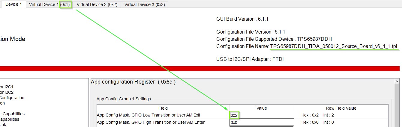
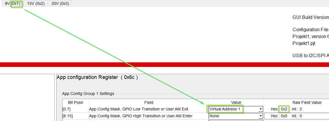
A customer of mine woule like to use a GPIO to select the max power that TPS65987D is delivering to a connected USB device. I only found the option to create two different configurations which seperate supply voltages and currents (register 0x32), but not with a power limit. 

How can a max power limit be selected? This feature is available on TPS25740 via the PCTRL pin. 

Background of the question: there is one big power supply which supplies multiple TPS65987D. Each TPS acts as charger for a conntec USB device. And the power supply tells the TPS via a GPIO if it is allowed to draw 60W or 30W. 

Thanks,
  Robert

  • Hello Robert,

    Your idea is the best implementation. Using the configuration tool, you will create two different configurations that would be loaded depending on the connection to a GPIO, using the App Config GPIO setting. You can reference the Power Duo Source or Sink board as a reference.

    http://www.ti.com/tool/TIDA-050012

  • Hi Adam,

    I downloaded the configuration tool and firmware for TIDA-050012. On that I have two questions:

    1. Under I/O config there are the push button events e.g. "Port 0 Load App Config 2" How does the assignment to these PDO's work? How can I assign AppConfig no. A to PDO no. B?
    2. There is no limitation of power. Just voltage and current. If I limit the voltage to lets say 15V/3A to achieve 45W maximum limitation. Is this conform to the power delivery standard? What happens if the mobile device needs 20V/1A? Can this happen according to the standard?

  • Hi Tim,

    1. If you look at the schematic, you will see that each push button goes to a GPIO with a specific purpose of loading a new configuration to change the source capabilities (9V, 15V, 20V). Each of the GPIO's have a GPIO event tied to them that will load their specific configuration. Ex. GPIO 1 loads App configure 1 which is virtual device 1 which is programmed to change the source capabilities to 9V 
    2. Yes that conforms to the PD standard. And in order for the phone to be complaint it has to be able to sink standard PDO values up to 20V (5V, 9V, 15V, 20V), so if the charger can only support up to 15V, then the phone and charger would negotiate a 15V contract.

    Hope this helps answer your questions

  • Hi Adam,

    thank you for the explanation. My FAE will send me the evaluation board then I can get familar with the IC.

  • Hi Adam.

    I got my board and I was dealing with the GPIO configuration.

    I had some trouble because of some bugs with the Application Customization Tool (version 6.1.1). I will explain them here so others won't run into the same issues:

    1. The GPIO polarity shown by the GUI is wrong (see corresponding bitfields in datasheet)

    2. The mapping of the App Config Groups to the Virtual Devices is very strange if you use the TIDA50012 template as a start of your development. It is mandatory to know that Virtual Device 1 corresponds to the hex value 0x02, Virtual Device 2 to hex value 0x04, Virtual Device 3 to hex value 0x08, etc.

    3. If you start with a new template (Project - New Project - ...) this becomes a little more obvious. Because then a selection dropdown field appears.

    Hope this helps some people. Maybe you can fix it soon.

    Best regards,

    Tim