


Part Number: DP83869HM
Other Parts Discussed in Thread: DP83869
Good day,
I am using the DP83869 in a design, and am currently struggling with strapping for the address and functional mode. The problem I have is that this PHY is connected to a microcontroller that have pull-ups enabled at boot. The pins can provide between 68uA to 250uA of current. Only after booting can I disable these pull-ups, causing the PHY to boot with the wrong address and functional mode, as I did not ass any external resistors :
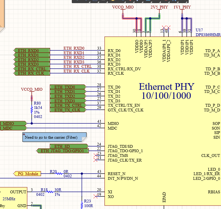
For the functional mode, I would simply add 2K pull-down resistors on RX_D2 and RX_D3. Note in my case that JTAG_TDO/GPIO_1 is not connected anywhere. The TI spec recommends a value of 2.49kohm, though:

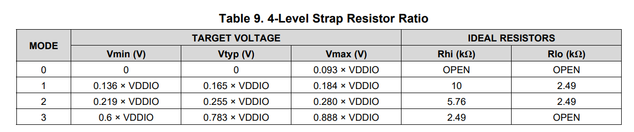
Now, with the strapping of the address, it is not so simple, as this time these pins have 4 possibles modes. Even without adding any resistors, I can theoretically go off-spec if my pull-up current is 250uA in the 9Kohm internal resistor of the PHY : 250u*9K = 2.25V. My VDDIO is 2.5V, so this is a 0.9VDDIO, exceeding the recommended max of 0.888VDDIO. Initially, I wanted to use mode 0 for both pins, but this would force me to use a small resistor (arround 1K) as pull down. I don't know if that is acceptable from the PHY standpoint. I could also use mode 3 and use an external pull-up, but again, I would be exceeding the maximum 0.888VDDIO requirement.
So my questions are the following :
1. Is it OK to use a 2K resistor instead of the 2.49K as pull-down for the functional mode straps?
2. How low can a strapping pull-down resistor be?
3. In 4-level strap, what requirement prevents exceeding 0.888VDDIO for mode 3?
Thank you!
Olivier
