This thread has been locked.

If you have a related question, please click the "Ask a related question" button in the top right corner. The newly created question will be automatically linked to this question.

DS90UH947-Q1: Pattern Generation Test

Part Number: DS90UH947-Q1
Other Parts Discussed in Thread: ALP

Hi Team,

My customer is using DS90UH947-Q1 / 948 and their display to test the pattern generation test. 

They refer http://www.ti.com/lit/an/snla132e/snla132e.pdf And they have a issue showing on display. (Afther 5 mins, the display is somehow flicker, the phenomenon isn't frequently.)  

Pattern selection : Full-screen User-Configurable Color (Gray scale)

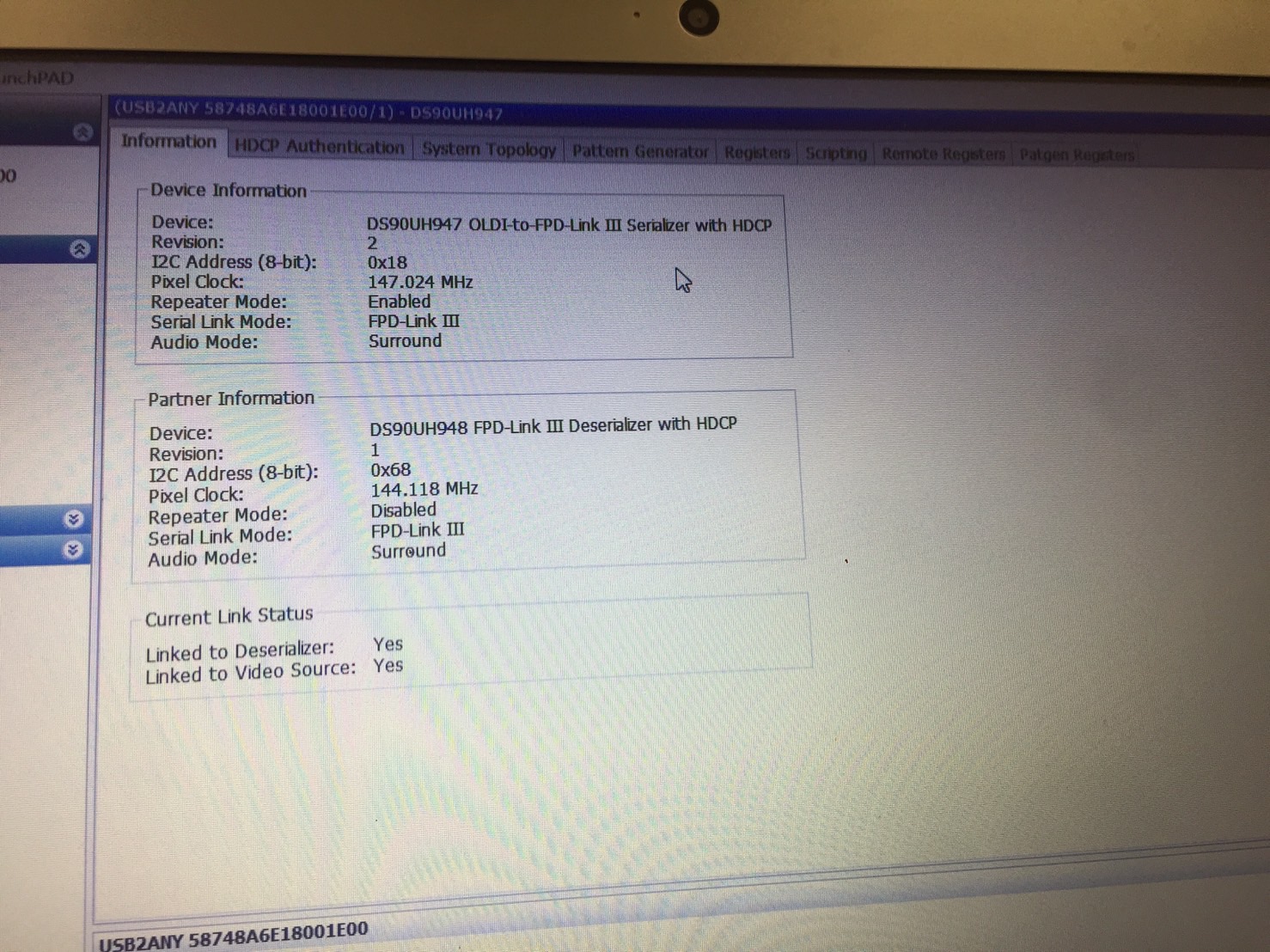
We think the issue is from timing setting from 947. Could you let us know the rule of serializer register setting when the display spec is showing as below.
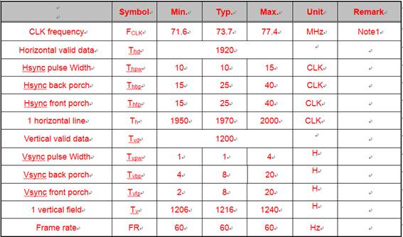
Display spec.

Current setting.

uint8_t serInitCode6[] = {0x4f, 0x40};

uint8_t serInitCode7[] = {0x66, 0x07};
uint8_t serInitCode8[] = {0x67, 0x80};

uint8_t serInitCode9[] = {0x66, 0x08};
uint8_t serInitCode10[] = {0x67, 0x07};

uint8_t serInitCode11[] = {0x66, 0x09};
uint8_t serInitCode12[] = {0x67, 0x4B};

uint8_t serInitCode13[] = {0x66, 0x04};
uint8_t serInitCode14[] = {0x67, 0xB2};

uint8_t serInitCode15[] = {0x66, 0x05};
uint8_t serInitCode16[] = {0x67, 0x07};

uint8_t serInitCode17[] = {0x66, 0x06};
uint8_t serInitCode18[] = {0x67, 0x4C};

uint8_t serInitCode19[] = {0x66, 0x0C};
uint8_t serInitCode20[] = {0x67, 0x19};

uint8_t serInitCode21[] = {0x66, 0x0D};
uint8_t serInitCode22[] = {0x67, 0x05};

uint8_t serInitCode23[] = {0x66, 0x0A};
uint8_t serInitCode24[] = {0x67, 0x0A};

uint8_t serInitCode25[] = {0x66, 0x0B};
uint8_t serInitCode26[] = {0x67, 0x01};

uint8_t serInitCode27[] = {0x66, 0x0E};
uint8_t serInitCode28[] = {0x67, 0x00};

Bist_P_num=0x11;

uint8_t serInitCode29[] = {0x65, 0x0C};
uint8_t serInitCode30[] = {0x64, Bist_P_num};

Thank you for your support.

Regards,

Roy

  • Hello Roy,

    I don't think this is the issue but all of your programmed timings fall in the typical column except for VBP which is programmed for 5 but the typical column says 8. 

    What PCLK rate are you supplying to the 947? Have you measured the input PCLK with a scope to confirm the frequency?

    Best Regards,

    Casey 

  • Hi Casey,

    I suggest customer modify the uint8_t serInitCode15[] = {0x66, 0x05}; to uint8_t serInitCode15[] = {0x66, 0x08};

    The PCLK = 150MHz (external OSC) Do you have any idea of possible factor that generate the issue?

    Regards,

    Roy

  • Hello Roy,

    Again I don't think this is the issue but with the timing parameters you have set, the actual frame rate will be slightly higher than 60Hz using 150MHz external clock: 

    150MHz/(1970*1216) = 62.6Hz

    So if you want to target 60Hz exactly then you may need to adjust this slightly. However if the display is running 5 minutes without issue then this doesn't really sound like a timing issue. For the system you are using are the 947 and 948 boards custom? Or is this using TI EVMs? Also what type of cable configuration is used between the two. When the flicker happens does the LOCK pin drop low on the 948 side?

    Best Regards,

    Casey 

  • Hi Casey,

    Sorry for omitting the information to you. The issue is from external clock because customer used jumper wire to connect the SerDes. And 947, 948 boards is custom.

    Just would like to double check the points showing as below

    Sec4.3 is custom display configuration, if we have a custom display, we could follow the 4.3 to make pattern generation, right? and its frame rate is set by PCLK and the calculation is PCLK/(horizontal valid data * vertical valid data) ?

    Sec4.4 is the example of 1080p60 with external clock example. And the latest issue is that frame rate is only 30 in display, but supposed to be 60(~150MHZ/1920/1080) we measure the rate of FPD-link lane is 75MHz (This is dual link operation) Do you have any idea which register setting that we may miss? 

    And what is the function of sec4.5?

    Regards,

    Roy

  • Hello Roy,

    Yes section 4.4 of the app note is an example for external clock mode which may be followed in this case. Frame rate is set by the following formula:

    PCLK/(horizontal total data * vertical total data)

    For this panel it is dual LVDS which means each LVDS input is running at half rate (~75MHz). If you supply 947 with 150MHz then use dual mode, each FPD-Link channel will operate at 75MHz. 

    Can you please check on my other questions:

    - What type of cable is being used?

    - When the screen flickers is lock dropping on the 948?

    Best Regards,

    Casey 

  • Hi Casey,

    Please see below comments. 

    - What type of cable is being used?

    STP

    - When the screen flickers is lock dropping on the 948?

    The flicker issue is fixed. The reason of flicker is showing in previous window.

    And the latest issue is that frame rate is only 30 in display, but supposed to be 60 in our design(~150MHZ/1920/1080) we checked the rate of FPD-link lane is 75MHz (This is dual link operation) Do you have any idea which register setting that we may miss? 

    Regards,

    Roy

  • Hello Roy,

    If you are using dual mode and each lane is 75Mhz then the total PCLK is 150MHz which should correlate to 60Hz. How are you determining that the display is seeing 30Hz?

    Best Regards,

    Casey 

  • Hi Casey,

    We used the CA310 Display Analyzer Instrument to measure the frame rate.

    Now we have measure the following frequency. (We use external clock 150MHz add in 947)

    1. 947(pin57 and pin58) = 150MHz

    2. STP frequency = 75MHz/lane (dual) 

    3. 948(pin36 and pin37) = 75MHz

    4. 948(pin23 and pin24) = 75MHz

    5. Display frame rate : 30 Hz

    Do you have any idea which factor may make display frame rate = 30Hz? 

    And could we have method to measure the PCLK frequency without using CLK pin and lane connector?

    Because I'm entry level in this application, I'm not familiar with 947/948. Thank you for your patient support.....

    If there is any specific word that I use wrong, please feel free to tell me. Thank you.

    Regards,

    Roy  

  • Hello Roy,

    If 948 is outputting 75MHz on each CLK1/2 then the combined PCLK value should be 150MHz so I don't think the issue would be coming from the SERDES. Maybe we need to check the panel configuration to ensure that it is set up to receive dual OLDI input?

    Best Regards,

    Casey 

  • Hi Casey,

    Should we check the specific register to verify the value in register is correct or not?

    I ask that because customer change the 0x4F register (bit 6 from 0 to 1)in the begining.

    bit 6 : 0 -> there is no picture on display

    bit6 : 1 -> there is picture on display but only 30Hz

    Regards,

    Roy 

  • Hi Casey,

    I have some questions after today's measurment and would like to have your comments.

    Today’s summary. Do the pattern generation test (SNLA132E sec.4.4)


    ////////////////////////////////////////////////////////////////////

    1. Without using ALP and use external clock 150MHz

                   a. Dual – link, but frame rate only 30Hz

                                                                   i.      Speed : 75MHz/per lane

                                                                 ii.      947 pin 58/57 : 150MHz

                                                                iii.      948 pin 37/36 : 75MHz

                                                               iv.      948 pin 24/23 : 75MHz

     2. Without using ALP and use external clock 100MHz

                   a.Dual – link, but frame rate only 30Hz

                                                                   i.      Speed : 75MHz/per lane

                                                                 ii.      947 pin 58/57 : 100MHz

                                                                iii.      948 pin 37/36 : 75MHz

                                                               iv.      948 pin 24/23 : 75MHz

    We could know the SerDes didn’t use external 150MHz OSC. And the question are showing as below.

    1. Why the SerDes didn’t get the external clock
      1. Could I do the extra command to let SerDes use external clock?
      2. Which register could we check?

    ////////////////////////////////////////////////////////////////////

     ///////////////////////////////////////////////////////////////////

    1. Use ALP and external clock 150MHz

              a. ALP shows PCLK in 947 and 948 is 150MHz

              b. SerDes went single link mode and lane speed is 100MHz


    2.Use ALP and external clock 70MHz

      1. ALP shows PCLK in 947 and 948 is 70MHz
      2. SerDes went single link mode and lane speed is 100MHz

    And the question is showing as below.

    1. Why FPD-link III went single link mode.
    2. Why Pattern generation use the internal clock

    ////////////////////////////////////////////////////////////////////

    Thank you for your help.

  • Hello,

    Please provide the code for the cases which you mentioned which are not using ALP.

    Non-ALP:

    Case 1 looks correct. If 948 is outputting 75MHz on each port then the total PCLK is 150MHz which should provide 60Hz based on the panel timing specification you provided. The only way it would not is if the display is not properly set up to accept a dual OLDI source. Please confirm that the display is set up correctly to receive dual OLDI. 

    Case 2 doesn't make sense. If 947 is receiving 100MHz, then the 948 can't output 75MHz per channel. There is no way that this can happen so I don't think the result is correct. 

    ALP:

    Case 1 The ALP tab shows the correct frequency for both SER and DES so I don't see why you are saying the DES is single link 100MHz. Where are you seeing that?

    Case 2 Again, if 947 input clock is 75MHz there is no way for the link to output 100MHz. The result does not make sense. Again, where are you seeing this?

    Also for ALP I do not see the "Enable Generator" box checked. That box needs to be set in order to enable the generator configuration. 

    Best Regards,

    Casey 

  • Hi Casey,

    Non-ALP: Means we do the sec4.4 pattern gen command with external clk without using ALP 

    Case 1 looks correct. If 948 is outputting 75MHz on each port then the total PCLK is 150MHz which should provide 60Hz based on the panel timing specification you provided. The only way it would not is if the display is not properly set up to accept a dual OLDI source. Please confirm that the display is set up correctly to receive dual OLDI. 

    So sec4.4 is dual OLDI output D[7:0] by default, right? I have one idea. Because we set the register 0x4F to 0x40(single pixel) and display showed the pattern, but by default value of 0x4F register is 0x00 (dual)  and display couldn't showed the pattern. I have no idea what is the relationship between this.

    Case 2 doesn't make sense. If 947 is receiving 100MHz, then the 948 can't output 75MHz per channel. There is no way that this can happen so I don't think the result is correct. 

    Yes, I'm confused about the result, too.....

    ALP:

    Case 1 The ALP tab shows the correct frequency for both SER and DES so I don't see why you are saying the DES is single link 100MHz. Where are you seeing that?

    Because we use external 150MHz clock here, but pattern gen in ALP only could choose up to 100MHz PCLK, so we measure the FPD-LINK AC cap and find FPD-link only operate in single link mode and the speed is 100MHz. But we didn't modify the setting after using ALP.

    Case 2 Again, if 947 input clock is 75MHz there is no way for the link to output 100MHz. The result does not make sense. Again, where are you seeing this?

    75MHz is external clk, and ALP shows 947/948 PCLK is 75MHz, but pattern generation PCLK we remain setting 100MHz. so we measure the FPD-LINK AC cap and find FPD-link only operate in single link mode and the speed is still 100MHz.

    We are considering that 947/948 did the pattern generation without using external clock but using internal clock. Could we have method to verify the point and fix? 

    Also for ALP I do not see the "Enable Generator" box checked. That box needs to be set in order to enable the generator configuration. 

    I will checked this point.


    Thank you.

    Regards,

    Roy

  • Also for ALP I do not see the "Enable Generator" box checked. That box needs to be set in order to enable the generator configuration. 

    yes, enable gen is check(O)

  • Roy, 

    Can you send the display panel datasheet? Also can you share schematics for the display panel which includes the connection information of the 948 to the display timing controller?

    Best Regards,

    Casey 

  • Hi Casey,

    I would like to tell the detailed condition first. We did the steps showing as below.

    1. Do the section 4.4 in SNLA132 (we connect a external CLK = 150MHz in 947 pin 57/58)

    2. ALP information shows 947/948 clock is 33MHz (we consider that the 947 not using external clk, it's using internal clk)

    3. We set address 0x4F data from 0x00(default value) to 0x40. 

    4. ALP information shows 947/948 clock is 150MHz (947/948 is using external clock now.)

    5. But frame rate is only 30. it should be 150M/1920/1080=60

    Question is showing as below

    1. Why we should set 0x4F address but this step is not showing in SLNA132

    2. why frame is only 30.

    Regards,

    Roy

  • Hi Casey,

    I use our 947/948 EVM board to do the internal pattern generation.

    Before doing the pattern generation, I find that the 0x4F default value is 0x40.

    But our custom 947 board 0x4F default value is 0x00. Do you have idea what factor may cause two difference default value? And our SLNA132 don't mention the step for 0x4F address.

    So I still have two questions.

    1. Why we should set 0x4F address but this step is not showing in SLNA132

    2. why frame is only 30.

    For display information, I send you the email due to confidential information.

    Regards,

    Roy

  • Hello Roy,

    0x4F is set from the MODE_SEL strapping. Please see the 947 datasheet for MODE_SEL information. In this case you are supplying 150MHz single OLDI to the 947 which means you want to set MODE_SEL0 = #1

    For the frame rate of 30Hz we have no explanation for it. It looks like the FPD-Link PATGEN setup is generating the correct timings and PCLK based on what you provided. If the display is not outputting the correct frame rate based on that, then the display provider needs to be consulted. 

    Best Regards,

    Casey 

  • Hi Casey,

    Below setting is custom 947 board. Because we set OLDI_DUAL = 1 (which means dual pixel mode), so our 0x4F default value is 0x00.

    So the pattern gen should be generated by single pixel mode? Could we use double pixel mode to use internal pattern generation? because pattern gen is used for testing. In real case we will use double pixel mode.

    Regards,

    Roy

  • Hello Roy,

    If you are using Dual OLDI input mode, then the PCLK input to 947 should be 150MHz/2 = 75MHz. If you are using single OLDI input to the 947 then you would set the 947 input clock to 150MHz. You can see the breakdown in the last post of this thread: https://e2e.ti.com/support/interface/f/138/t/724062?tisearch=e2e-sitesearch&keymatch=ds90ub947%2520pclk%2520frequency%2520dual

    Best Regards,

    Casey 

  • Hi Casey,

    Excuse me. Could you let me know if our internal pattern generation could run by address 0x4F = 0x00? (dual pixel mode) 

    Regards,

    Roy

  • Hello Roy,

    Yes, PATGEN can be run with dual pixel mode, 0x4F = 0x00. If you want to do this and you want to send 150MHz total PCLK, then the PCLK input to 947 should be 75MHz. 

    Best Regards,

    Casey 

  • Hi Casey,

    But I couldn't run pattern generation with dual pixel(0x4F = 0x00)(display couldn't show the pattern). Do you have any idea that the possible reason or any setting that we should do? (besides PCLK setting)

    BTW, could we use PCLK divider to change external CLK value? 

    ps. If I set 0x4F from 0x00 to 0x40(single pixel mode) and display could show the pattern on it.

    Roy 

  • Roy,

    If 0x4F = 0x00 and you supply 150MHz PCLK to the 947 it will try to generate 300MHz PCLK because it is dual pixel mode. So if you set 0x40 = 0x00 then please use 75MHz PCLK to generate the correct 150MHz combined frequency during both normal mode and PATGEN with external clock mode. I believe this is the issue you were seeing. 

    Best Regards,

    Casey 

  • Hi Casey,

    Thank you for your support, I will use 75MHz PCLK to do the measurement again.

    In addition, in real case they will use use dual OLDI input and dual link(STP), in this operation should we use PCLK = 150MHz or 75MHz?

    Regards,

    Roy

  • Roy,

    For both PATGEN and normal mode it is the same. In dual OLDI input mode (0x4F = 0x00), the PCLK input to 947 should be 1/2 the total PCLK (75MHz in this case).

    Best Regards,

    Casey 

  • Hi Casey,

    But in https://e2e.ti.com/support/interface/f/138/t/724062?tisearch=e2e-sitesearch&keymatch=ds90ub947%2520pclk%2520frequency%2520dual

    Davor said that 150MHz should be fed. Is any misunderstand to me?

    I would like to check below operation : 1080p 60Hz

    single pixel mode -> 947 ->dual link -> 948 =>PCLK = 150MHz

    dual   pixel mode -> 947 ->dual link -> 948 =>PCLK =    75MHz

  • In single OLDI input mode you would feed 150MHz. In dual OLDI input mode you would feed 75MHz. Again, please see the table Davor provided in the last post of the thread. 

    Regards,

    Casey 

  • Hi Casey,

    Got it. Thank you for your support. We will keep the measurement, if there is any updated test, I will let you know.

    For 30fps issue, I will go customer LAB to collect the information.

    Could you let me know the critical information that you would like to know?(SerDes schematic and display information are sent to you.)

    Regards,

    Roy

  • Roy,

    Please confirm that the deserializer is also set for dual OLDI output mode, not single. Also please confirm the PCLK at each deserializer clock output is 75MHz. 

    Best Regards,

    Casey 

  • Hi Casey,

    If we use external clock = 75MHz and operation is showing as below. This video output is normal. (1080p frame=60Hz)

    If we use external clock = 150MHz and operation is showing as below. This video output is abnormal. (1080p frame=30Hz)

    Do you have any idea which factor may cause frame rate different?

    Regards,

    Roy

  • Roy,

    As I have explained several times: If you supply 75MHz input PCLK then you must set Dual OLDI mode for combined 150MHz output PCLK (0x4F = 0x00).

    If you supply 150MHz PCLK with dual OLDI mode selected (0x4F = 0x00), it is not a valid configuration for the device because dual OLDI mode expects input PCLK to be between 12.5MHz and 85MHz. 

    Regards,

    Casey 

  • Hi Casey,

    I understand your points.

    I mean I set valid configuration in single pixel mode(external clk=150Mhz) and dual pixel mode(external clk=75MHz) 

    But the frame rate result is different. Single pixel mode is 30Hz and dual pixel mode is 60Hz.

    I think they should be the same due to frame rate = 150M/Horizantal/Vertical 

    Regards,

    Roy

  • Hi Casey,

    Do you have any comments?

    I did the SLNA132 section4.4 action with single pixel mode and double pixel mode.

    Why the frame rate result showing on display is different?

    double pixel mode = 60Hz

    single pixel mode = 30Hz

    Roy

  • Hello Roy,

    I do not know how to explain any further than we have discussed. I suggest you block out a time for us to discuss on the phone if support is still needed. 

    Best Regards,

    Casey 

  • Hi Casey,

    okay, I will make a slide and the we could have a concall, I will send you the e-mail.

    Regards,

    Roy