This thread has been locked.

If you have a related question, please click the "Ask a related question" button in the top right corner. The newly created question will be automatically linked to this question.

TPS65981: DISC 4CC command has no effect

Part Number: TPS65981
Other Parts Discussed in Thread: BQ25703,

In our design, we have a step that changes from supply 5V via PP_EXT to PP_5V0config. This is approximately what happens

1. 5V is being supplied via PP_EXT

2. We receive a request for PP_EXT to be set at a different voltage. 

3. In Tx source capabilities register, set PDO0NotSourcedbyPP5V0 to 0

4. Send DISC command to force the power path to switch

5. Bring PP_EXT up to 9V (or some other voltage)

The goal is for the port to receive 5V, disconnect briefly, and then receive 5V from the other power path. What I see though is that the DISC command does not disconnect the port or change the power path. Furthermore, this sequence of inputs seems to have bypassed the overvoltage detection, and I end up actually supplying 9V to a non PD peer that should be receiving 5V. This is definitely a bug, and somewhat dangerous as well. I know that step 3 is in general correct, because if I manually reconnect the usb port, it receives the correct voltage.

The DISC command is returning success, and I have not customized the lock code in any way. Is there a way to get DISC to work, or a workaround to achieve what I want?

  • Hi Jerry,

    Why are you wanting to source 5V between different power paths? Your procedure is not the standard use case for the TPS65981, so it does not surprise me that you are running into issues.

    If you want to supply 5V and 9V, I suggest having PP5V0 be dedicated to your 5V supply and PP_EXT be dedicated to your 9V supply.

  • We have a product with 2 usb ports connected to  a single PP_EXT line -- this allows a single BQ25703 to supply 9V to both usb ports. This requires switching the ports between PP_5v0 and PP_EXT.

    Whether it is the standard use case shouldn't be a consideration. We chose the TPS65981 for its feature set and customization. If a feature is documented in the data sheet then it should work and be supported. 

  • Would you be able to share a block diagram of your system? From your post, I still believe that the BQ25703 can supply 9V to both PP_EXT power paths, and have the PP5V for the TPS65981 remain at 5V. Is the battery charger supplying both the 5V and 9V voltages? Are you only wanting one Type-C port to advertise 9V at a time.

    As far as the DISC, you need to read the output data from the TPS65981 to see if the task was completed successfully (in this case simulate a disconnect), or if the task was rejected. If the task was rejected, then that is why the TPS65981 did not disconnect the ports as the task was not completed successfully.

  • Also, would you be able to share an I2C capture when you send the DISC 4cc command? I can double check that your implementation of the 4cc command is correct.

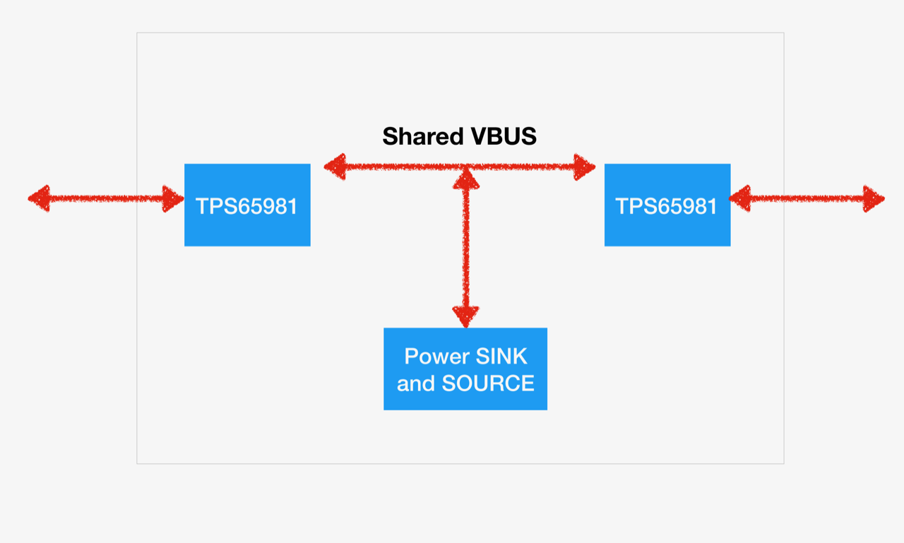
  • Here is a simplified box diagram. The Power sink and source is a BQ25703 connected to a removable battery. The shared vbus allows one battery to provide otg voltage to two different usb ports, and allows voltage from a sink port to be provided to the other port in source. The BQ25703 can supply any voltage, we have an LDO that converts the voltage on VBUS to 5V to provide PP_5V0. 

    By usb rules, vbus on an unattached port must be 5V, even if we are advertising 9V.

    To reiterate, we have 2 cases:

    1. Sink is plugged in to port 1. We supply 5V through PP_EXT. A 9V contract is accepted on port 1, so we supply 9V through PP_EXT and switch both ports to use PP_5V0. Sink is plugged in to port 2, and receives 5V. Everything works as expected

    2. Sink is plugged in to port 2. We supply 5V through PP_EXT. Another sink is plugged into port 1, receives 5V through PP_EXT, then a 9V contract is accepted on port 1. We switch both ports to using PP_5V0 and perform DISC on port 2 to ensure that it has fully transitioned to that power path. We then supply 9V on PP_EXT. However DISC had no effect so port 2 is actually on PP_EXT instead of PP_5V0 and is getting 9V(!) somehow bypassing the overvoltage check as well.

    By output data do you mean "Table 4-1. Standard Task Response"? We see 0x0 "task completed successfully" when sending the DISC command. We're using an argument of 1 for a 1 second delay until reconnection. My equipment is limited right now as well, but I'll try to get an i2c capture.

  • Hi Jerry,

    Thank you for sharing. Will take a look at this and provide feedback early next week

  • Hi Jerry,

    Thanks for the additional details. I tested the TPS65981EVM here in the lab and the DISC seems to be working as expected for me. One thing that you can test is when this 4cc command, measure VBUS/CC1/CC2/PP_5V0. The DISC 4cc command removes the pullup and pulldown resistors on the CC lines, so it would be a good measurement to make sure that this is occurring.

    You can also try issuing the HRST command to see if the results for that line up with what you are expecting.

    Once again I would recommend changing this architecture to where the PP5V power path is always used for sourcing the 5V from the LDO. Your power architecture for both devices would be PP5V to source 5V, PPEXT to source 9V - 20V, and PPHV to sink 5V - 20V. When you have a device connected that can sink more than 5V, you will update the voltage supplied to PPEXT, update the source capabilities of the PD controller, and then issue the SSrC 4cc command. This will force the PD controller to send out the updated source capabilities, and then the two devices will negotiate a 9V contract.

    This type of architecture will make sure that there is no voltage drop on the other Type-C port, and you will know with 100% certainty that where all of the voltages are being supplied or sinked from at any given time.