This thread has been locked.

If you have a related question, please click the "Ask a related question" button in the top right corner. The newly created question will be automatically linked to this question.

TCAN1042-Q1: how Icc spec varies with ambient temperature Ta?

Part Number: TCAN1042-Q1

Team, 

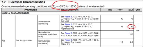
My customer is looking at the Normal mode (dominant) 5V-Supply current (Icc). They think max current parameter 80 mA considers Ta = 125C. Could you please help us understanding how Icc spec varies with ambient temperature Ta? They are looking for Icc when Ta = 85C and Ta = 95C.

Thanks

Viktorija

  • Hi Viktorija,

    In the recessive state there isn't much temperature dependence - you can see this in Figure 3 of the datasheet. For the dominant state the ICC is dependent mainly on the voltage (VOD) driven onto the bus (which will cause a current equal to VOD/R, where R is the resistive loading of the bus due to termination, etc.).  You can see the VOD variation versus temperature in Figure 1.

    Given the flatness of both these curves it is probably best to design based on the maximum spec value.  Let me know if this doesn't make sense.

    Regards,
    Max

  • Max, 

    Thanks for the response, that explains a lot. I would like to verify my understanding.

    Icc depends on VOD/R where R is termination resistor @ that bus. If we use following equation to estimate max Icc,

    Icc = (VOD/R)) + (10% of VOD/R); 10% margin on top of the calculation (to estimate max current, Icc).

    Is this acceptable? 

    Considering following:

    • Termination resistor is 120 ohm
    • VOD = 5V (I think this is really high, trying to get the worst case number)

    For this case, Icc = (VOD/R)) + (10% of VOD/R) = (5/120)+(10%*(5/120)) = 45.8 mA.

    With termination resistance 120 ohm, Is 45.8 mA a fair max Icc estimation?

    Please let us know your thought on the calculation.  

  • Viktorija,

    Yes, the calculation makes sense, but consider that the bus will likely be 60 ohm for R since there will be two 120 ohms in series. And it's fine to assume the worst case with 5V if you just want to over-spec the current consumption to be safe, but at 120 or 60 ohm termination on the bus, VO(D) wouldn't be 5V max, it would be closer to 3V max, 2V typical.

    Is the 10% just for add margin?

    Regards,

    Eric Hackett

  • Eric, 

    Reason for considering margin: I was trying to correlate the 70/80 mA spec (from datasheet) with Icc ≈ VOD/R equation. If R is 60/50 ohm, VOD (max) is 3V, Icc (max) ≈ 50 mA/ 60 mA, wondering how to correlate 70/ 80 mA?


    Please let us know your thought.

    Thanks

    Viktorija 

  • Viktorija,

    The 70mA and 80mA are attributed to extreme temperature conditions, high VCC and VOD as a result, along with taking the worst possible condition to make sure users design their systems properly and without risk of damage or danger in their application.

    Let’s use this diagram to simplify things a bit: the 0.5V are forward diode drops, the two 20 ohms are the RDSon of the FETs when the dominant signal is being driven in the transceiver, and 60 ohms is the termination resistance. Ignoring the bias unit, VCC = 5V, and there are 2 x 0.5V diode drops that leaves 4V / (60 + 20 + 20) = 40mA in the typical case shown in the datasheet.

    For the maximum case dominant current, this is for the worst-case, and for this measurement that means extreme temperatures along with high VCC and VOD levels. What happens at temperature corners is the diode voltage drop and the RDSon both decrease. With this happening, there is less of a decrease in VCC from the diode drop, and more of the voltage is dropped over the termination resistance since there’s less overall resistance and thus more current. So say the diode drops decreases to 0.25V, and the RDSons decrease to 10 ohms, and VCC is still 5V. That leaves (5V – 0.5V) / (10 + 60 + 10) = 56.25mA. Not quite the maximum of 70mA shown in the datasheet, but if VCC supplied is 5.5V, we have (5.5V – 0.5V) / (10 + 60 + 10) = 62.5mA. 

    So as you can see, as conditions become more and more extreme, the dominant current increases. The maximum case is meant to consider every worst possible condition so the user of this device will design their system without risking damage in case any or all of those conditions occur.

    Regards,