This thread has been locked.

If you have a related question, please click the "Ask a related question" button in the top right corner. The newly created question will be automatically linked to this question.

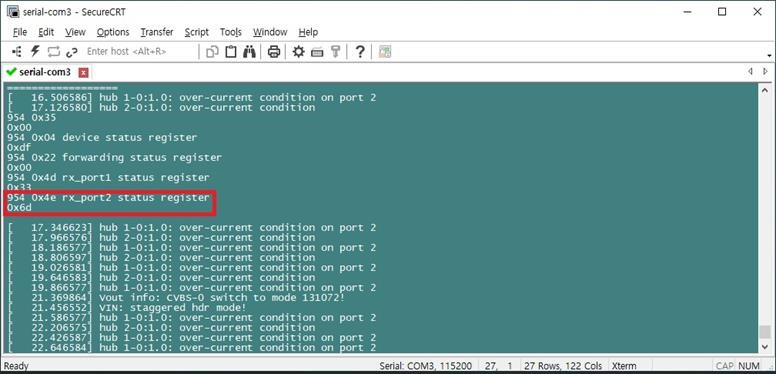
DS90UB954-Q1: ub954, 0x4E (RX_PORT_STATUS2) error of 0x6D.

Part Number: DS90UB954-Q1

Dear Sir,

My customer is debugging DS90UB954-Q1.
When read 0x4E register After Initialization. the value is 0x6D
Could you advise me debugging point?

  • Hello,

    What is the MODE strap setting for 954 and what serializer device is connected to the port?

    Best Regards,

    Casey 

  • Dear Casey,

    Mode is non sync, and they are using DS90UB953 for Serializer.

    please refer to the attached schematics.

    2161.TI-DS90UB954-Q1 Schematic.pdf6472.TI-DS90UB953-Q1 Schematic.pdf

  • Hi Dexter,

    Can you please try reading this particular register twice, read it, wait about 5-10 seconds, then read it again. This is because there's multiple bits in there that are Clear on Read (COR) and can be set during initialization but are not real faults. Let's first ensure that these are actual errors.

    Regards,
    Mandeep Singh

  • Dear Mandeep,

    Now we are testing Sync mode.

    we had read status register after initial.

    the result is as below.

    could you check status register and let me know that check point?

    954 0x04 device status register, 0xdf value ok

    0xdf


    954 0x35 csi_status register, 0x03 value ok

    0x01


    954 0x22 forwarding status register, 0x01 value ok

    0x00


    954 0x4d rx_port1 status register, 0x03 value ok

    0x13


    954 0x4e rx_port2 status register, 0x00 value ok

    0x0c


    954 0x7a csi_rx status register, 0x00 value ok

    0x02


    954 0x51~0x54 sensor status register, 0x00 value ok

    0x00

    0x00

    0x03

    0x00

  • Hi Dexter,

    Most of the registers are showing expected results, you have LOCK and PASS which is good. I just had some comments on 2 of the registers below. By the way, are you getting any issues with the video? or are you just trying to understand the results of the registers and video output is okay?

    Register 0x4d[5] = 1 means the lock status changed, this is a COR register, so read this twice to ensure the lock is not constantly dropping.

    Register 0x7a indicates that you have ECC errors on the CSI data. This is also COR register, are you reading this twice or just once after initialization? If so, please read this twice and share the results.

    Regards,
    Mandeep Singh

  • Hi Mandeep,

    could you help as below situation. please let me know any advise to me.

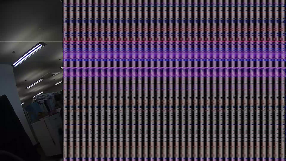
    1. actual image is abnormal as attached capture.


    2. When the Status register is read twice, it is displayed as shown below.

    # i2cget -y 0 0x30 0x4d bb

    0x3b

    # i2cget -y 0 0x30 0x4d bb

    0x03

    # i2cget -y 0 0x30 0x7a bb

    0x0f

    # i2cget -y 0 0x30 0x7a bb

    0x0c


    3. The image sensor output is set to 1920x1080. However, if you read the 0x73 ~ 0x76 register, it is strange. The number of lines is normally read as 1080, but it is strange that the line length is read as 2880.


    # i2cget -y 0 0x30 0x73 bb

    0x04

    # i2cget -y 0 0x30 0x74 bb

    0x38

    # i2cget -y 0 0x30 0x75 bb

    0x0b

    # i2cget -y 0 0x30 0x76 bb

    0x40


  • Hi Dexter,

    Please see my comments below

    0x4D = 0x03 #looks good, you have lock

    0x7a = 0x0c #You are getting length and checksum errors. This can be because the imager is not transmitting CSI data correctly or the data is getting corrupted during the transmission.

    0x73, 0x74 = 0x04, 0x38 # Hex to decimal = 1080 (as expected)

    0x75, 0x76 = 0x0b, 0x40 # Hex to decimal = 2880, the register reads as 8-bit, but you are transmitting data as 12 bit, therefore you have to do a conversion. (2880*8)/12 = 1920 (as expected)

    The main issue I'm seeing is that you are getting CSI errors. Can you try the following steps.

    1) Turn on PatGen on the 954 and capture the results.

    2) If results are good, then proceed to turn off PatGen on the 954 and Turn on Patgen on the 953 and capture/share the results.

    Regards,
    Mandeep Singh

  • Hi Mandeep Singh,

    Could you please check PatGen Image for 954 and 953. looks like the PatGen image is abnormal.

    can you advise me any comment for the PatGen images.

    1. 954 PatGen Enable
    2. Register setting

    i2cset -y 0 0x30 0xB0 0x00 bb

    i2cset -y 0 0x30 0xB1 0x01 bb

    i2cset -y 0 0x30 0xB2 0x01 bb

    i2cset -y 0 0x30 0xB1 0x02 bb

    i2cset -y 0 0x30 0xB2 0x33 bb

    i2cset -y 0 0x30 0xB1 0x03 bb

    i2cset -y 0 0x30 0xB2 0x24 bb

    i2cset -y 0 0x30 0xB1 0x04 bb

    i2cset -y 0 0x30 0xB2 0x16 bb

    i2cset -y 0 0x30 0xB1 0x05 bb

    i2cset -y 0 0x30 0xB2 0x80 bb

    i2cset -y 0 0x30 0xB1 0x06 bb

    i2cset -y 0 0x30 0xB2 0x02 bb

    i2cset -y 0 0x30 0xB1 0x07 bb

    i2cset -y 0 0x30 0xB2 0xD0 bb

    i2cset -y 0 0x30 0xB1 0x08 bb

    i2cset -y 0 0x30 0xB2 0x04 bb

    i2cset -y 0 0x30 0xB1 0x09 bb

    i2cset -y 0 0x30 0xB2 0x38 bb

    i2cset -y 0 0x30 0xB1 0x0A bb

    i2cset -y 0 0x30 0xB2 0x04 bb

    i2cset -y 0 0x30 0xB1 0x0B bb

    i2cset -y 0 0x30 0xB2 0x65 bb

    i2cset -y 0 0x30 0xB1 0x0C bb

    i2cset -y 0 0x30 0xB2 0x0B bb

    i2cset -y 0 0x30 0xB1 0x0D bb

    i2cset -y 0 0x30 0xB2 0x93 bb

    i2cset -y 0 0x30 0xB1 0x0E bb

    i2cset -y 0 0x30 0xB2 0x21 bb

    i2cset -y 0 0x30 0xB1 0x0F bb

    i2cset -y 0 0x30 0xB2 0x0A bb

    954 PatGen Image Capture


    1. 953 PatGen Enable
    2. Register setting

    i2cset -y 0 0x0c 0xB0 0x00 bb

    i2cset -y 0 0x0c 0xB1 0x01 bb

    i2cset -y 0 0x0c 0xB2 0x01 bb

    i2cset -y 0 0x0c 0xB1 0x02 bb

    i2cset -y 0 0x0c 0xB2 0x33 bb

    i2cset -y 0 0x0c 0xB1 0x03 bb

    i2cset -y 0 0x0c 0xB2 0x24 bb

    i2cset -y 0 0x0c 0xB1 0x04 bb

    i2cset -y 0 0x0c 0xB2 0x16 bb

    i2cset -y 0 0x0c 0xB1 0x05 bb

    i2cset -y 0 0x0c 0xB2 0x80 bb

    i2cset -y 0 0x0c 0xB1 0x06 bb

    i2cset -y 0 0x0c 0xB2 0x02 bb

    i2cset -y 0 0x0c 0xB1 0x07 bb

    i2cset -y 0 0x0c 0xB2 0xD0 bb

    i2cset -y 0 0x0c 0xB1 0x08 bb

    i2cset -y 0 0x0c 0xB2 0x04 bb

    i2cset -y 0 0x0c 0xB1 0x09 bb

    i2cset -y 0 0x0c 0xB2 0x38 bb

    i2cset -y 0 0x0c 0xB1 0x0A bb

    i2cset -y 0 0x0c 0xB2 0x04 bb

    i2cset -y 0 0x0c 0xB1 0x0B bb

    i2cset -y 0 0x0c 0xB2 0x65 bb

    i2cset -y 0 0x0c 0xB1 0x0C bb

    i2cset -y 0 0x0c 0xB2 0x0B bb

    i2cset -y 0 0x0c 0xB1 0x0D bb

    i2cset -y 0 0x0c 0xB2 0x93 bb

    i2cset -y 0 0x0c 0xB1 0x0E bb

    i2cset -y 0 0x0c 0xB2 0x21 bb

    i2cset -y 0 0x0c 0xB1 0x0F bb

    i2cset -y 0 0x0c 0xB2 0x0A bb

    953 PatGen Image Capture


  • Hi Dexter,

    The captures are typically black and white, is the pink color because of the processor? Perhaps it's not translating the color to black and white. Looking at this quantitatively between the ser and the des, the captures look similar and normal. In comparison to your capture, we are no longer seeing a disrupted capture like what you were capturing earlier from the imager. This could mean a few things listed below.

    1)The imager is outputting corrupted data which is what we're seeing at the processor.

    a) Have you captured the CSI data directly from the imager without the serdes?

    2) This could be an issue with the processor not being able to capture all the data.

    a) What is the resolution (hactive, Vactive, Hblank, Vblank), fps, data type of the imager?

    Regards,

    Mandeep Singh

  • Hi Mandeep,

    please check below answer and let me know any advise me like that.

    1. When the imager and cpu are attached directly without sedes, the image is output normally.
    2. Hactive=1920, Vactive=1080, Hblank=1668, Vblank=32, fps=30, data type= AMBA_VIN_INPUT_FORMAT_RGB_RAW

  • Hi Dexter,

    I'm not sure what are the Bits per pixel for that data format but even if it was RGB888, it would still be under the 3.2G CSI input limit. However, is that video format CSI-2 compliant?

    Can you capture the patgen of the 954 by setting just the 3 registers below. It should be a black and white capture with 8 bars. I'm not sure if something else is getting changed in the registers you are setting, this will help ensure that patgen is being captured properly.

    0xb0 = 0x00

    0xb1 = 0x01

    0xb2 = 0x01

    Regards,
    Mandeep Singh

  • Hi Mandeep,

    It is good working to change image sensor.

    Thank you for your support.