This thread has been locked.

If you have a related question, please click the "Ask a related question" button in the top right corner. The newly created question will be automatically linked to this question.

DP83867CS: DS83867

Part Number: DP83867CS

Hi Sir,

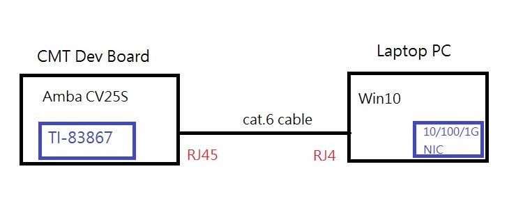
My customer working on TI DP83867 Ethernet PHY bring-up this week.

Right now, we can see eth0 in Linux but can’t get any response by ping.


1. The frequency of CLK_OUT is 25MHz.

    It should be 125MHz because of RGMII.

    Do we need to change register IO_MUX_CFG (0x170) setting?

2. MDIO seems not work?

    The read back phy id (through function: get_phy_id()) is always 0.

    But from the driver, it should be 0x2000a231.

    I’m not sure is it the root cause, so dp83867 (phy_driver) can’t attach to the phydev->mdio.dev.driver.

    It turns out that genphy_driver was registered in function: phy_attach_direct().


3. I check the source code and the spec, the device address is 0x1f.

    Should I assign this address to .dts?


As my customer response, TI helped one of their customer bring up DP83867 on AMBA CV22 chip last week.

Please help us figure out the root cause.


===

This is what I change:


1. built-in linux-4.14/drivers/net/phy/dp83867.c into Linux kernel

2. define mac0 in .dts.


              mac0: ethernet@e000e000 {

                  status = "ok";

                     pinctrl-0 = <&rgmii_pins>;

                     /*amb,ahb-12mhz-div = <5>;*/

                     amb,tx-clk-invert;

                     /*amb,int-gtx-clk125;*/

                     /*amb,ext-ref-clk;*/

                     phy-mode = "rgmii";

                     phy@0 {

                         compatible = "ethernet-phy-ieee802.3-c22";

                           reg = <31>;                             ß should I assign 31 (0x1f) here?

                           rst-gpios = <&gpio 25 0>;

                           ti,rx-internal-delay = <DP83867_RGMIIDCTL_2_25_NS>;

                           ti,tx-internal-delay = <DP83867_RGMIIDCTL_2_75_NS>;

                           ti,fifo-depth = <DP83867_PHYCR_FIFO_DEPTH_4_B_NIB>;

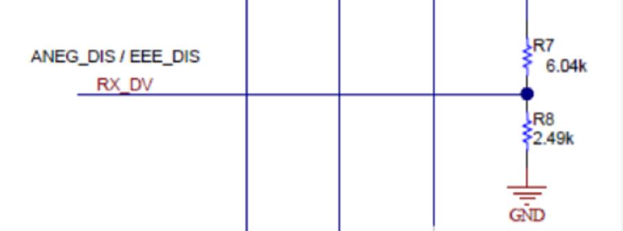
                           ti,dp83867-rxctrl-strap-quirk;

                           enet-phy-lane-swap;

                     };

              };

 Thanks, Ian.

  • Hi Ian,

    Can you please share the strap configuration on pin rx_d0 and rx_d2 (phy_id pins) and led_0 pin (rgmii/sgmii configuration)? 

    What do you see on rx_clk? Is there a crystal attached to phy or is the clock on xi coming from external clock source?

    --

    Regards,

    Vikram 

  • Hi Sir,

    Can you please share the strap configuration on pin rx_d0 and rx_d2 (phy_id pins) and led_0 pin (rgmii/sgmii configuration)?

    [A] Use Ethernet PHY default setting [00].

    What do you see on rx_clk? Is there a crystal attached to phy or is the clock on xi coming from external clock source?

    [A] From external clock source, the PHY U53.32 pin RX_CLK(ENET_CLK_GRX) is connected to CV25 U6.M1 pin ENET_CLK_RX.

    Thanks, Ian.


  • Hi Sir,

    Would you pls help to advise?

    Thanks, Ian.

  • Hi Ian,

    It can be power up sequence issue. You can try following :

    1. Check that whether clock connected to XI is already stable before the supply of the phy is stable? (recommended case).

    2. If not, then once the clock is stable (25MHz) and power of phy is up, do try reseting the phy using resetn pin.

    See if register values are read correctly then.

    --

    Regards,

    Vikram

  • Hi Vikram,

    MDIO is working now, but still can’t get response by ping.

    ps. Do I need to change register 0x0170 setting? The external clock is 25MHz.

    The CLK_OUT of DP83867 is actually 25MHz.

    Right now, bit [12:8] of register 0x0170 is 01100.

    I also dump some register for you as reference.

    Register 0x0170 = 0xc0d

    Register 0x006E = 0x0.

    Register 0x006F = 0x0.

    Register 0x0032 = 0xd3.

    Register 0x0010 = 0x5048

    Register 0x0001 = 0x7949

    We try all combinations of register 0x0170.

    Except 0xC, all setting (0x0 ~ 0xB) leads CLK_OUT outputs 125Mhz.

    But I still can’t get any response by ping.

    What else I can do?

    Thanks, Ian.

  • Hi Vikram,

    please help confirm the current Linux driver strap settings? Maybe I can add pull high or low resistance from the outside.

    In addition, please confirm that all the strap is default [00], can the RGMII mode work normally?

    Thanks, Ian.

  • Hi Ian,

    You need not write anything in register 0x0170 for ping to work. From register 0x0001, I dont see that the device is linked up with other device over copper cable. Please send the following :

    1. Block diagram of the your test setup.

    2. Speed configuration of link-partner

    3. Is 867 in auto-neg mode or forced speed mode?

    4. Can you try writting 0x001F = 8000 and share register values of 0x0000, 0x0001 before and after it (in your ping setup).

    --

    Regards,

    Vikram

  • Hi Vikram,

    0.  You need not write anything in register 0x0170 for ping to work.

    From register 0x0001, it didn’t see that the device is linked up with other device over copper cable. Please send the following :

    ->

    0.1  I modified the driver not to change the register “0x0170”,  the DP 83867 initializing log as below,

    ->

    [    4.121484] dp83867_config_init(218)

    [    4.125230] dp83867_config_init(237) DP83867_CFG4 = 4272

    [    4.130696] dp83867_config_init(243)

    [    4.134470] dp83867_config_init(261) DP83867_STRAP_STS2 = 0x0

    [    4.140365] dp83867_config_init(264) DP83867_STRAP_STS1 = 0x0

    [    4.146134] dp83867_config_init(272)

    [    4.149859] dp83867_config_init(276) DP83867_RGMIICTL = 0xd3

    [    4.155829] dp83867_config_init(295)

    [    4.159554] [rodney_debug]: dp83867_config_init(312) 0x0010 register = 0x5048

    [    4.166829] [rodney_debug]: dp83867_config_init(314) 0x0001 register = 0x7949

    [    4.174107] [rodney_debug]: dp83867_config_init(318) read DP83867_IO_MUX_CFG (0x0170) = 0xc0e

    [    4.182720] dp83867_config_init(218)

    [    4.186443] dp83867_config_init(237) DP83867_CFG4 = 4144

    [    4.191902] dp83867_config_init(243)

    [    4.195667] dp83867_config_init(261) DP83867_STRAP_STS2 = 0x0

    [    4.201562] dp83867_config_init(264) DP83867_STRAP_STS1 = 0x0

    [    4.207331] dp83867_config_init(272)

    [    4.211057] dp83867_config_init(276) DP83867_RGMIICTL = 0xd3

    [    4.217031] dp83867_config_init(295)

    [    4.220758] [rodney_debug]: dp83867_config_init(312) 0x0010 register = 0x5048

    [    4.228036] [rodney_debug]: dp83867_config_init(314) 0x0001 register = 0x7949

    [    4.235315] [rodney_debug]: dp83867_config_init(318) read DP83867_IO_MUX_CFG (0x0170) = 0xc0e


    0.2  After the modification, the result is:

    ENET_CLK_GTX-> 25MHz

    ENET_TX_EN-> low (Even if there is no signal output, it should be high level)

    ENET_TXD0/D1/D2/D3-> low (Even if there is no signal output, it should be high level)


    ENET_RXDV-> low       ( it was  the clock signal 125MHz before.)

    ENET_CLK_GRX-> 25MHz

    ENET_RXD0/D1/D2/D3-> low (Even if there is no signal output, it should be high level)


    CLK_OUT-> 25MHz


    1. Block diagram of our test setup.

    ->As  picture below:


    2. Speed configuration of link-partner

        We tested link-partner in auto-neg, 1G, 100M, 10M speed.


    3. Is 867 in auto-neg mode or forced speed mode?

        We used auto-neg  mode on 83867 by default configuration from HW strap configuration & FW driver.


    4 Can you try writting 0x001F = 8000 and share register values of 0x0000, 0x0001 before and after it (in your ping setup).

    # phytool read eth0/0x0/0x0001

    0x796d

    #

    # phytool read eth0/0x0/0x0000

    0x1140

    # phytool write eth0/0x0/0x001F 8000

    #

    # phytool write eth0/0x0/0x001F 8000

    # phytool read eth0/0x0/0x0001

    0x796d

    #

    # phytool write eth0/0x0/0x001F 8000

    # phytool read eth0/0x0/0x0000

    0x1140


    One more question,

            There is only one  different strap configuration between TI-EVM and customer DEV-board as below picture.

           If we have to modify HW strap like TI-EVM so the default FW driver can meet the corresponding HW setting ?

    Thanks, Ian.

  • Hi Ian,

    I see link up after you wrote 0x001F=8000. Reg0x0001[2]=1. It was 0 earlier.

    Do you see ping after you do write 0x001F=8000? 

  • Hi Vikram,

    We see link up after you wrote 0x001F=8000. Reg0x0001[2]=1. It was 0 earlier.

    Do you see ping after you do write 0x001F=8000?

    ->Ping command is still fail after writing 0x001F=0x8000


    ->the log as below:

    # phytool read eth0/0x0/0x0000

    0x1140

    #

    # phytool read eth0/0x0/0x0001

    0x796d

    # phytool write eth0/0x0/0x001F 0x8000

    #

    # phytool read eth0/0x0/0x0000

    0x1140

    #

    # phytool read eth0/0x0/0x0001

    0x796d

    #

    # ifconfig

    eth0      Link encap:Ethernet  HWaddr AA:EA:36:55:D6:2F

              inet addr:192.168.0.200  Bcast:192.168.0.255  Mask:255.255.255.0

              UP BROADCAST RUNNING MULTICAST  MTU:1500  Metric:1

              RX packets:7896 errors:0 dropped:0 overruns:0 frame:0

              TX packets:6692 errors:0 dropped:0 overruns:0 carrier:0

              collisions:0 txqueuelen:1000

              RX bytes:565174 (551.9 KiB)  TX bytes:371212 (362.5 KiB)

              Interrupt:28


    lo        Link encap:Local Loopback

              inet addr:127.0.0.1  Mask:255.0.0.0

              UP LOOPBACK RUNNING  MTU:65536  Metric:1

              RX packets:283 errors:0 dropped:0 overruns:0 frame:0

              TX packets:283 errors:0 dropped:0 overruns:0 carrier:0

              collisions:0 txqueuelen:1000

              RX bytes:30640 (29.9 KiB)  TX bytes:30640 (29.9 KiB)


    # ping 192.168.0.192

    PING 192.168.0.192 (192.168.0.192): 56 data bytes


    --- 192.168.0.192 ping statistics ---

    27 packets transmitted, 0 packets received, 100% packet loss

    #

     Thanks, Ian.


  • Hi Vikram,

    One more question about TMCH_CTRL(0x25).

    On spec default should be 0x400 on normal.

    But I find if I don’t connect to eth cable the value is 0x0, After connection cable the value change to 0xc1e1.

    Does it normal??

    Thanks, Ian.

  • Hi Ian,

    Link is up after writting 0x001F=8000 but Rgmii is still not working.

    Lets read register 0x0032 and see the status of Rgmii. Bit 7 should be 1 in Rgmii mode. If it is not 1, then lets try over-writting this bit7 to be 1 and check if rx_clk starts toggling at 125MHz.

    Also do share the schematic so that I can review the hardware straps and see what's connected on led_0 pin.

    --

    Regards,

    Vikram

  • Hi Ian,

    No it is not expected to change and it should show as 0x0400. You mentioned earlier that there was some problem with MDIO read/write. How was it resolved? It looks like register read write issue only.

    --

    Regards,

    Vikram