This thread has been locked.

If you have a related question, please click the "Ask a related question" button in the top right corner. The newly created question will be automatically linked to this question.

TCA8418: RTWR

Part Number: TCA8418

I am not getting an interrupt generated from this device. I have KEY_INT connected to a 10ku resistor as pullup. Not getting any interrupt when I press the keys. Using arduino interface via esp32. tca8418 library from phishman. Any help would be appreciated.

  • Hey Khary,

    Are you able to provide us a register read of all the registers you wrote when you initialized the device?

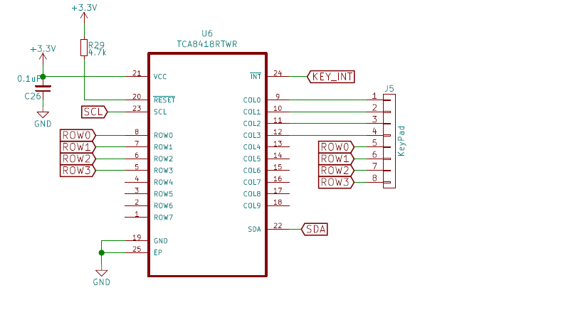
    Do you have a schematic for us to review?

    Any o-scope shots of the SDA/SCL pins when you do reads/writes?

    Thanks,

    -Bobby

  • What pullup resistor should i use for KEY_INT on pin 24. I tried 10k and it seemed to hang the system. I am working on getting you the other info oscilloscope etc...

  • //Configure for a 4X4 matrix on COL0-COL4, ROW0-ROW4 and enable interrupts
    Keypad.begin(ROW0|ROW1|ROW2|ROW3, COL0|COL1|COL2|COL3,
    CFG_KE_IEN|CFG_AI|CFG_INT_CFG|CFG_GPI_E_CFG);

    these may be the wrong bits for a 4x4 keypad. The 3rd row enables the interrupts Is this correct or I need different?

    this is the default...

    //Configure for a 4X4 matrix on COL0-COL4, ROW0-ROW4 and enable interrupts
    Keypad.begin(ROW0|ROW1|ROW2|ROW3, COL0|COL1|COL2|COL3,
    CFG_KE_IEN|CFG_OVR_FLOW_IEN|CFG_INT_CFG|CFG_OVR_FLOW_M);

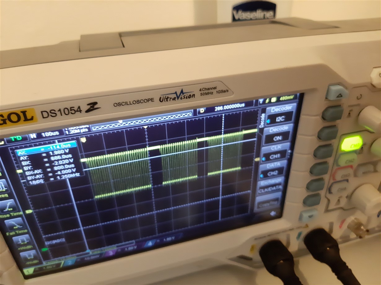
  •  This is what i get on the scope at the key_INT pin 24 on tca8418

  • Hey Khary,

    For the register values, can you provide me with the read values from each register? I am not with the software/code you are using so the code you provided does not help me understand what is doing on.

    Something like:

    0x01h = >>insert hex value here<<

    0x02h = >>insert hex value here<<

    ect.

    "What pullup resistor should i use for KEY_INT on pin 24. I tried 10k and it seemed to hang the system."

    The INT resistance does not matter too much. The smaller value you use, the more power consumption you will use but in return you will have a strong pull up bias on the pin. 10k should be fine.

    For the o-scope picture. It looks like you re probing the SCL line, I would expect the INT to not toggle as much as it currently is.

    I've like to see an I2C transaction of both SDA/SCL to ensure communication looks okay.

    -Bobby

  • OKAY on the 0x01 register I have 187 so interrupts are enabled it seems to do one write. then the 0x01 register reads -1. THis happens after I press the button. what do you think is going on here...>>?

  • Bobby could it be that I don't have the unused pins connected to a pullup ? Should I connect the unused pins to a pullup?

  • I haven't seen a schematic of your set up yet. What unused pins do you have floating?

    -Bobby

  •  this shows the unused pins do these need to be connected to vcc through a pullup

  • Your schematic looks fine.

    You have a decoupling cap.

    Pinout matches datasheet.

    Net names match the pin names.

    Pull up is seen on the reset.

    "do these need to be connected to vcc through a pullup"

    You can tie the rows to a 10k pull up resistor if you want to but its not 100% required.

    ---------------------------------

    "OKAY on the 0x01 register I have 187 so interrupts are enabled it seems to do one write. then the 0x01 register reads -1. THis happens after I press the button. what do you think is going on here...>>?"

    So 187 in decimal is 0xBBh. If you are writing 0xBBh in register and reading 0x01h after then it sounds like you are not properly writing to the device. You should be able to read what you write into register 0x01h.

    Take a scopeshot of the SDA/SCL pins when you do a write to 0x01h. Make suore you get an ACK from the device when you write the data in.

    -Bobby

  • I amable to read what I put in . I put in 187 and that's what i'm reading. The issue is after i press the key the bus goes unresponsive.

  • Can you verify what data is in register (before and after a button press):

    0x1D

    0x1E

    0x1F

    0x03

    After pressing a button, you should see an INT get triggered in which reading 0x02 should tell you what caused the INT.

    Reading 0x03h should tell you how many key events have been collected (2 if you press and then release 1 button)

    Reading register 0x04h should tell you which button was pressed (read again to see the button being released)

    This all assumes though that you configured 0x1D/0x1E/0x1F correctly to be part of the keypad matrix.

    -Bobby