This thread has been locked.

If you have a related question, please click the "Ask a related question" button in the top right corner. The newly created question will be automatically linked to this question.

AM26C31: AM26C31 used to make a NMEA buffer

Part Number: AM26C31
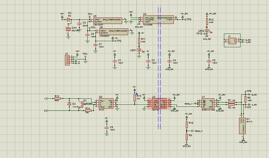
Other Parts Discussed in Thread: THVD2450, SN65HVD1785, ISO7721

Hi everybody,

I'm working on an NMEA buffer. I'd like to use my nmea0183 signal from my GPS (RS485) to other equipments (AIS, VHF...).

I've found this component AM26C31 which seems to be the right one.

So what I do :

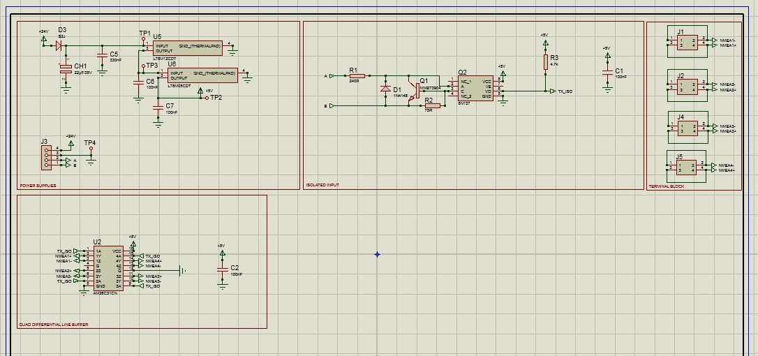
- Receive my NMEA signal from my GPS, isolated it through an optocoupler (6N137) and then the signal goes to AM26C31.

So my question is, can I connect one output from my optocoupler to the 4 inputs of AM26C31 without any problems ? Is there no problems with impedance or capacitance ?

Moreover, I think my +/- from my input will be inverted on my output ? I need to re-inverted them.

Thank you in advance for your answer,

Fabrice

  • Hi Fabrice,

    Could you connect the NMEA signal to the "C" input of 6N137 while "A" is pulled up?  That way the LED would be on when the NMEA signal is low.  As far as I understand from the 6N137 datasheet, that would prevent requiring an extra signal inversion.  Then, the question would just be whether 6N137 can drive four parallel AM26C31 inputs.  Each input consumes a current of at most 1 uA (see "II" specification), and the open-drain output of the detector side of the 6N137 seems to be able to sink fairly large currents (they spec at 13 mA).  So, I don't see any issue with this connection.  I'd just be sure you use a single pull-up resistance on the optocoupler output in the 330 Ohm - 4.7 kOhm range as recommended in that part's datasheet.

    If you want us to check over your schematic once you draw it up just for an additional check just let us know.

    Regards,
    Max

  • Hi Max,

    Thank you for answer, it was that I was thinking.

    When my design will be done, I'll submit it.

    Another point, I'd like to be sure, I'd like also isolated the outputs.

    I didn't find (for the moment) a component which mades the same thing as the AM26C31 but with galvanic isolation.

    As NMEA sentences are in one way (only GPS to receiver), I consider to add four ISO7721D between AM26C31 outputs and my terminals.

    Do you think is it feasible ?

    Or instead of the previous design, I can keep my 6N137 for input and add four ISO7721D + four SN65HVD1785d  (I've checked about input/ouput current, it's ok), the cost will be higher than the first solution.

    Because which bothers me in the first solution, it's that my solution for isolation is located after the line driver, for me it's not correct (about bus protection...).

    Thank you in advance for your advices,

    Fabrice

  • Hi Max,

    Please find below my design. Now, I'm just thiking about how to isolated the four outputs.

    Fabrice

  • Hi Fabrice,

    The AM26C31 implementation looks good to me, although it would be a general best practice to pull unused digital input (like the G pin) high or low so that they are in a defined state.  You may want to the 6N137's vendor to review that implementation since they will have better expertise on it.

    Regarding isolation, this is typically done on the digital signals (TX_ISO in this case).  It would be more difficult to isolate the differential lines directly.  Since you already have the opto-coupler on for TX_ISO, though, why is additional isolation needed?

    Regards,
    Max

  • Hi Max,

    Thank you for your reply and your advice.

    Concerning the outputs, it can be connected up to four different listeners, that can be supplied by different ways, and to avoid any problems, that the reason why I'd like to isolate the outputs.

    Moreover, all outputs are from the same component (AM26C31), so if there is an electrical problem on one of the ouput, it can put this component out of order, more it's protected more it's safe !

    Regards,

    Fabrice

  • Hi Fabrice,

    That makes sense.  It sounds like using four separate transceivers (for example, 4x THVD2450) would help with making sure one channel's issues do not propagate to the the others (except via a shared VCC connection).  Or, if needed you could go a step further and have an independent isolated power supply for each channel and use an independent digital isolator (or opto-coupler) for each, although that would of course be more complex and costly.  In either case I think putting galvanic isolation on the digital IOs to the transceiver is the way to go - I don't know of any options for reliably isolating the differential signals directly.

    Max

  • Hi Max,

    Thank you for your answer, it was I was thinking.

    I have made a new design (only with one output for the moment, I just need to multiplicate this one 3 times).

    I've kept my isolated input by optocoupler. The input current of ISO7721D on INx is only 10µA (so I can connect four ISO7721D to the output of my optocoupler). On my side, I've the habit to use the SN65HVD1785, I think it's an equivalent of THVD2450.

    I'll have four DC/DC converter, it'll cost a little bit more, but il'll be more safe for me.

    I've only connected the OUTx of the ISO7721D because NMEA signal in only going in one way, for REDE, I'll connect it to ground.

    But I'll think about using an optocoupler to do that, it'll be cheaper I think.

    Thank you,

    Regards,

    Fabrice

  • Fabrice,

    Thanks for posting, I agree this design should be pretty robust.  I'm wondering why you would use both the opto-coupler and the digital isolator, though - could you not just directly connect your digital input to the ISO7721 input (rather than to the optocoupler)?

    Max

  • Hi Max,

    You mean that I need to connect directly NMEA input to the ISO7721 ? I need to transform the differential line to "TTL", so I need an opto-coupler or another SN65HVD1785 for the input.

    Maybe I didn't understand what you mean.

    Regards,

    Fabrice

  • Fabrice,

    That was my misunderstanding; I thought the NMEA output was already TTL.  In that case I see what you are doing here.  Thanks for the explanation.

    Max