This thread has been locked.

If you have a related question, please click the "Ask a related question" button in the top right corner. The newly created question will be automatically linked to this question.

DS160PR410: S-paras model results look way off

Part Number: DS160PR410

I downloaded the S-Params models for the part, and run a simulation in HYPERLYNX.

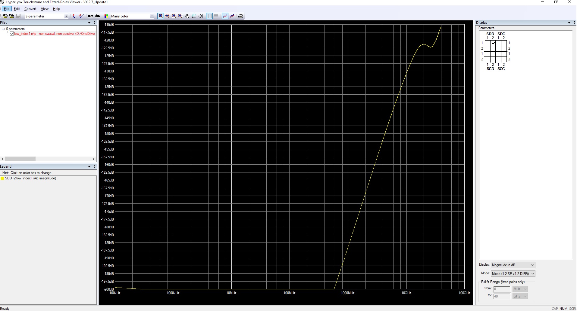
I used the low_index1 model, which was supposed to show a equalization of 0.4dB. Instead I am seeing ~-120dB

Something seems out of wack.

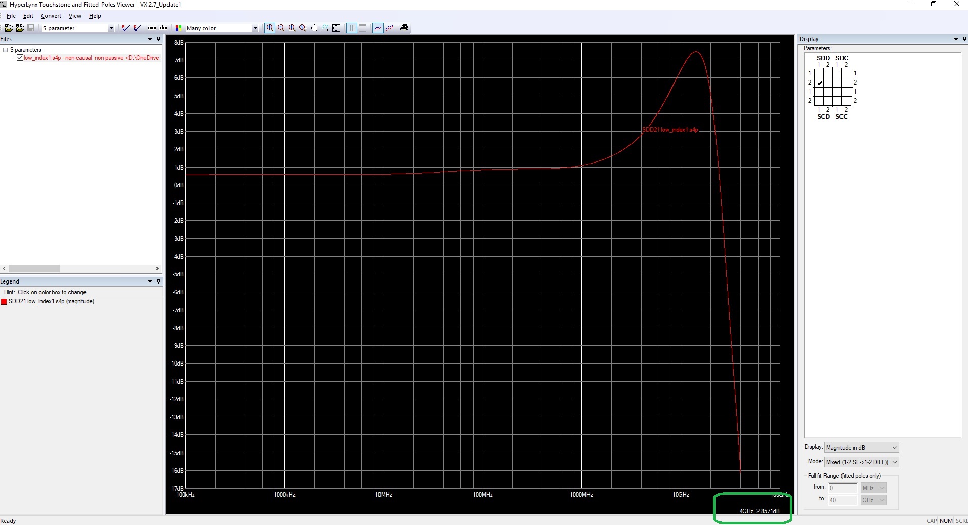
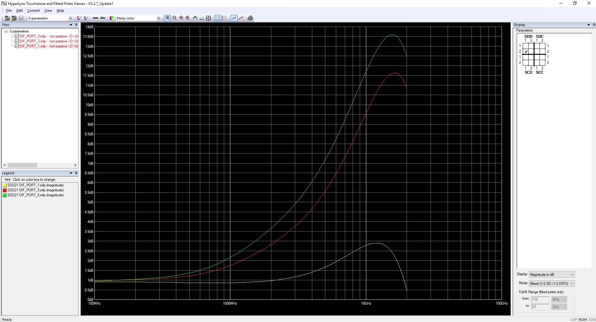
This is what I am doing in FreeSim and the results:

  • Hello-

    The DS160PR410 is a differential device.  You need to look at the differential insertion loss parameter (SDD12), not single-ended (S12).

    Regards,

    Davor

  • Davor,

    The SDD12 model you suggest I use, when using LOW_INDEX_1 model looks like this.

    The SDD21 looks more like the one from the data sheet:

    ...but this is still confusing, because TABLE 1 shows a gain of 0.4 @4GHz, but the model shows a gain of 2.85dB

    So, I'm still not sure how to use this model.

    Is the model made for the RX or for TX? Since SDD12 is so low, it seems to me that this is the model for the receiver and I have to use SDD21 for that, and not SDD12 as you suggested.

  • Hello-

    That was my mistake.  I was thinking SDD21, but mistakenly suggested SDD12.  I'm sorry for the confusion.

    Let me look into the 0.4 dB to 2.85 dB @ 4 GHz discrepancy to see if I can determine the root cause. 

    Regards,

    Davor

  • So, are you saying that the model is build such that input signal needs to go into ports 3/4 and output is on 1/2 ?

    I believe this would be quite opposite of what the User Guide suggests. According to Table 1. Model Information

    • DS160PR410_IBIS_AMI_Model
    – low_index0.s4p (1->2, 3->4)
    – low_index1.s4p (1->2, 3->4)

    ...

    Which seems to indicate that signal goes in, on port 1/3 and output is 2/4

    Looks like in fact the model is actually backwards. Could you please clarify?

    Does this mean I use the same model for the TX and RX channels, and just swap the ports?

  • Hello-

    The signal actually needs to go on ports 1/3 and the output is on ports 2/4 as suggested in the User's Manual.  I tried simulating it the other way around and the output eye diagram is a flat line.

    For an active device, the convention is that the S21 represents the power transferred from port 1 to port2 or a forward gain.

    The same model should be used for the TX and RX channels.

    I have also confirmed that the EQ_Index0 and EQ_Index1 S-parameter models were generated with wrong settings.  Other models are OK. We'll have the new models generated in a couple of days.  I will let you know when they are uploaded to mySecure.

    Regards,

    Davor

  • Yes, you are correct, my typo. Per User Guide signal should go in on 1/3 and out on 2/4 .

    But actually, based on the fact that SDD21 is only one that shows a viable plot,  it looks to me like the signal needs to flow from ports 2/4 to ports 1/3 

    As long as I know that this is how i'm supposed to use it, I'm fine. I would just like this to be clarified, because the UG seems to contradict the actual model.

    Regarding the RX/TX models: since the RX and TX are probably supposed to be identical in their behavior, I will simply take the same S-param model and use it both ways.

    Also, are you still trying to find out why the 4GHz value is different in the S plot than what it is specified in the data sheet table?

  • Hello,

    Yes. We've confirmed that the EQ_Index0 and EQ_Index1 S-parameter models were generated with wrong settings.  Other models are OK. We'll have the updated models generated in a day or two.  I will let you know when they are uploaded to mySecure.

    Regards,

    Davor

  • Davor,

    Are the corrected IBIS models ready? If so could you point me to them? First time I asked for them, I received a folder in my "secure software" on My TI page. I just checked and that link s no longer there.

  • Hello Traian,

    I've just uploaded the updated models. It typically takes no more than 30 minutes for these models to show up on mySecure site. However, I did check the external mySecure website and I also don't see any of the mySecure folders available (for this as well as for other devices).  I will raise this issue with the appropriate support team.  I assume this is just a temporary issue with the mySecure website.

    Regarding the updated models, note that the EQ boost values in the datasheet represent the delta between the values on the forward gain curves at 4 GHz (or 8 GHz) and DC values.

    Regards,

    Davor

  • I got the new models. Thanks.

    But I am still not sure how to read this. This is what I got for indexes 1, 3 and 5. The peaks are not quite where Figure 1 shows them

    According to that figure,

    index 1 should peak at ~5dB but the model peaks at 2.9dB

    index 3 should peak at ~15dB but the model peaks at 11.6dB

    index 5 should peak at ~16-17dB but the model peaks at 13.58dB

    What am I missing?

  • Hi Traian,

    The S-parameter models are simulated models while Figure 1 in the datasheet shows actual measurements.  We are aware that there is discrepancy between the  simulated and measured EQ gain curves.  However, given that the EQ gain can vary around  +/-2  dB at 8 GHz across PVT, the discrepancy is within the expected variation.

    Do you need any further info or I can consider this thread to be closed?

    Regards,

    Davor