This thread has been locked.

If you have a related question, please click the "Ask a related question" button in the top right corner. The newly created question will be automatically linked to this question.

TCA4311: little pulse waveform

Part Number: TCA4311

Hi Sir,

Below is my customer's design topology with TCA4311.

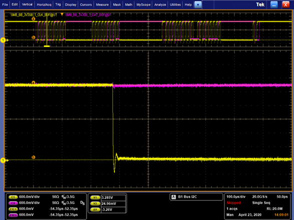
When they measurement the waveform in the test point, we will see the little pulse no matter I use TCA4311 or TCA9511 in the same place.

But we bypass TCA4311, the pulse will disappear.

Could you please help to comments on it?

Thank you

Test condition#1 with TCA4311


Test condition#2 with TCA9511

Test condition#3 bypass TCA4311/TCA9511

  • Hi Anne,

    Would it be possible to see the other side of the device as well? Is it being held low during all of these waveform captures?

    Thanks,

    Max

  • Hi Max,

    Here is the waveform capture from the other side of the device,

    And also share the schematic to you.

    Thanks

    CLK

    DAT

  • Hey Anne,

    I believe this blip is being caused by the driver initially yanking the line low very quickly. Afterwards our device tries to regulate the 'output' side to be whatever the input side voltage is plus the dynamic offset voltage. The internal amplifier may be a bit slow so it doesn't regulate the VoL+offset to its correct value quick enough which results in the larger blip you see on the opposite side. I assume if you add capacitance on both sides or make the pull up resistors weaker (like 10k) the blip will likely become less due to less current causing the overshoot. You could also put a series resistor infront of whatever device is driving the line low (something like 20 ohm) to dampen the di/dt when transitioning from high to low.

    Is the customer seeing any I2C communication problems? I expect something like this not to cause signal integrity issues.

    -Bobby

  • Hi Bobby,

    We reduce undershoot by changing R/pull up R ,but there still  a blip in TCA9511 output waveform .
    Do you have another suggestion to eliminate this problem?

  • Hey Anne,

    Is the blip actually causing signal integrity issues? This bump looks okay to me. The bump does not exceed 30% of Vcc and should not cause glitches on the bus.

    If you want to try to smooth the bump further, you would need to add bus capacitance which is not something we typically want to do because I2C spec restricts bus capacitance to 400pF for standard mode and fast mode.

    -Bobby