Part Number: TPS65987D
Other Parts Discussed in Thread: BQ25703A, , TPS65988, BQ25713, BQ25703
Hi,
Recently, I started using TPS6598x application customization tool (V6.1.1) to configure TPS65987D EVM board, and want to connect the board to BQ25703A EVM board. (Similar as TIDA-01627) I manually soldered jumper wire from R9 & R11 on TPS65987EVM (they were DNP-ed) to SCL/SDA on BQ25703A.
The R9 & R11 are connected to I2C3 of TPS65987D chip. Then I soldered a jumper wire from PP_HV1 of TPS65987D EVM board, then connect it to BQ25703A EVM board. Finally, I followed the SLVAE18 (Using I2C Master in TPS65987D and TPS65988 PD
Controllers), try to get the similar result. However, it does not work.
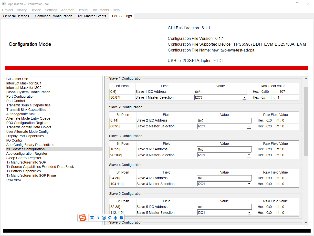
When I configured the TPS65987D I2C Master, the GUI shows that Slave 1 configuration bit position and register length are different than SLVUBH2B (TPS65987DDH and TPS65988DH Host Interface
Technical Reference Manual) writting. In SLVUBH2B P90 3.43, it has SlaveEnable field and SlaveAddr is at 7:1 of byte1 but the GUI indicate address is 0:6; And the length of register is 20 in GUI but 16 in SLVUBH2B.
And, I found that maybe a typo on the datasheet of bq25703A. "The I2C address is D6H (1101101_X)", bq25703A p31, 8.5 Programming. Based on its brother device BQ25713, I think this address should be 6B (bq25713, P4, 6 Device Comparison Table; ). I assume 1101011_X should be the corrent binary form of the BQ25703. Since 6B = 01101011, D6 = 11010110, they can be considered as same due to 7-bit address combined with r/w bit.
Could you please provide a configuration binary or project file of the configuration tool? I just wondering how can achieve this.
Attached is my project file. I really appreciated if you can point out where I was wrong.