This thread has been locked.

If you have a related question, please click the "Ask a related question" button in the top right corner. The newly created question will be automatically linked to this question.

TMDS181: Input AC coupling

Part Number: TMDS181
Other Parts Discussed in Thread: TMDS171

Hello,

Let me confirm about below.

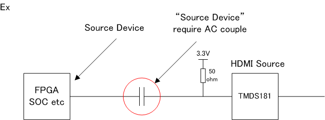
* Why TI recommend to use DP159 and DP149 when AC coupling is required on TMDS input line ?

(I referred following video.)

https://training.ti.com/jp/enhancing-system-performance-signal-conditioners

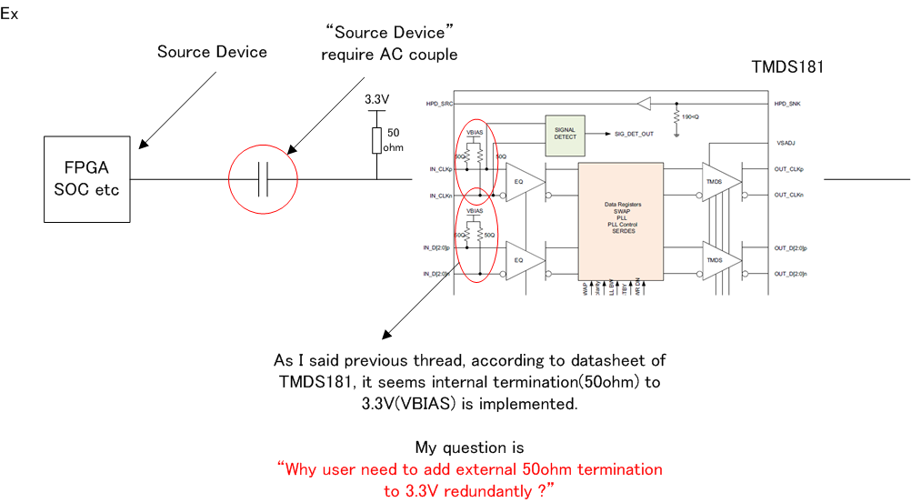
According to datasheet of TMDS171 and TMDS181 also have VBIAS(3.3V).

Actually, VBIAS voltage is different b/w TMDS1x1 and DP1x9, however, both have bias voltage inside device.

So, it seems that both series can accept AC coupling on TMDS input line.

So could you please confirm why TI said that only DP1x9 should be used for AC coupling requirement ?

Best Regards

  • If AC-coupling the TMDS181 input main link, then you need to add external 50ohm termination to 3.3V between the AC coupling cap and the TMDS181 on the main link. But the input Vh would then be above the 3.3V VCC depending on the input signal amplitude and this would stress the TMDS181 I/O.

    With DP159, you only need to AC couple the input main link, there is no need for external 50ohm termination to 3.3V.

    Thanks

    David

  • Hello David-san,

    Thank you for your reply.

    >If AC-coupling the TMDS181 input main link, then you need to add external 50ohm termination to 3.3V between the AC coupling cap and the TMDS181 on the main link.

    According to datasheet of TMDS181, it seems internal termination(50ohm) to 3.3V(VBIAS) is implemented.

    Why user need to add external 50ohm termination to 3.3V redundantly ?

    (If it is mistake of "you need to add external 50ohm termination to 3.3V between the AC coupling cap and the "source device"(Opposite of TMDS181), I can understand..)

    Best Regards,

  • Hi

    I am referring to the case which the source output requires to be AC coupled, you would then need external 50ohm to 3.3V between the AC coupling cap and the TMDS181 to mimic a DC-coupled HDMI source termination.

    Thanks

    David

  • David-san,

    I understood that you assume following case.

    And I understood that user need to add external termination(50 ohm) for TMDS data/clk as shown below from your reply.

    Is my understanding correct ?

    BR, 

  • Your block diagram is correct.

    Thanks

    David

  • David-san,

    OK. So let me re-confirm previous my following question.

    Could you please send feedback about above question of highlighted red ?

    BR

  • Sorry, you are right that there is no need for external termination since termination is already inside the TMDS181. So you only need the external AC coupling cap.

    If you connect an AC coupled signal to TMDS181 input, the signal will be mounted on 3.3V, depending on the amplitude of the signal Vh=3.3V+A and Vl=3.3V-A, here Vh will go above Vcc.

    If you connect an AC coupled signal to DP159 input, the signal will be mounted on 0.7V, depending on the amplitude of the signal Vh=0.7V+A and Vl=0.7V-A., here the signal is within GND and Vcc.

    So for a AC coupled signal, we recommend DP159.

    Thanks

    David

  • David-san,

    Thank you for your reply.

    >If you connect an AC coupled signal to TMDS181 input, the signal will be mounted on 3.3V, depending on the amplitude of the signal Vh=3.3V+A and Vl=3.3V-A, here Vh will go above Vcc.

    I have question about above sentence.

    According to datasheet, following specs are defined as shown below.

    max value of VIDpp : 1560mV

    max value of VICM : Vcc + 0.1V 

    Absolute max value of IN_Dx and IN_CLKx : Vcc + 0.3V

    I think that input signal will become out of spec in this case as well even though user use DC coupling.

    Here is my calculation.

    * VIDpp = VID+ - VID-

    * VICM = (VID+ + VID-) / 2

    When the max values are applied to above equation, result is as follows.

    * 1560mV = VID+ - VID-

    * 3.4V = (VID+ + VID-) / 2

    So, VID+ is 4.18V and VID- is 2.62V in this case.

    Actually, VID- is spec in Vcc-0.75(defined absolute value), however VID+ is spec out Vcc+0.3V.

    So, I'm not satisfied with your explanation. How do you think about above ?
    Best Regards,


  • Hi,

    HDMI uses current drive on the source side to develop the low voltage diff signal at the sink side. The termination voltage on the sink side sets the high voltage level of the diff signal. The low voltage is set by the current at the source and the termination resistance at the sink. 

    A compliant HDMI source should not drive the TMDS line exceeding the conditions being set in Table 4-23 of the HDMI spec. 

    Thanks

    David

  • Hello

    I understood why TMDS1x1 series is recommended to use DC coupling from your reply.

    Here is my understanding. (I focus Vih spec)

    * In case of DC coupling, actually input voltage never exceed recommended spec if user compliant HDMI spec.

    However, in case of AC coupling w/ TMDS181, input voltage become 3.3V + Vswing. So input voltage exceed absolute spec.


    Best Regards,

  • Your understanding is correct.

    Thanks

    David