This thread has been locked.

If you have a related question, please click the "Ask a related question" button in the top right corner. The newly created question will be automatically linked to this question.

DP83TC811S-Q1: TDR test enable procedure for DP83TC811S-Q1

Part Number: DP83TC811S-Q1
Other Parts Discussed in Thread: DP83TC811

Hi Team,

DP83TC811S-Q1 was test in customer side. Now they have a problem on TDR test enable procedure. Customer can't enable TDR test. 

Here is the action they did, could you check it for us and provide the right TDR test enable procedure? Thanks.

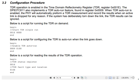
Step1: Enter Managed operation mode, write 0x0000 to register 0x018B;

Step 2:  Start TDR test, Write 0x8000 to register 0x0001e;

Step 3: Short Cable or Open Cable;

Step4: Read the value of register 0X016B, but the value is 0x0000.


BR

Songzhen Guo

  • Hello,

    Have you reviewed our application note that outlines the registers to configure TDR? Section 3 of this document should help you. Please let me know if you are still unable to configure properly after reviewing the document.

    http://www.ti.com/lit/an/snla291/snla291.pdf

    Thanks,

    Cecilia

  • Hi Cecilia,

    Thanks for you feedback. Customer follow the procedure, but they also can't get the result. Could you check it for customer? Thanks.

    There are other 3 actions of TDR test. Customer followed the step, here is the action and result:

    STEP1: The 1st requirement is changing the Master mode to Slave, and changing the slave mode to master freely.

    According to file of DP83TC811,which is screenshoted below,if the PMA_CTRL Register(0x0834) of the phy is wrriten to 0xC000, The phy should be a MASTER mode. If the same register is wrriten to 0x8000, the phy should be a SLAVE mode.

    Test result: The real test result is that the phy gets 0x0000 all the time,however, the mode can NOT be changed at all.


     Step 2: The 2nd requirement is entering and exiting the test mode.

    According to file,which is mentioned above,if the TEST_CTRL_Register(0x0836) is wrriten to 0x2001, 0x4001,0x8001 or 0xA001; the phy will enter Test Mode 1,Test Mode 2,Test Mode 4 or Test Mode 5.

    Test Result: The real test result is that the phy gets 0x0000 all the time,however, the test mode can NOT be changed at all

    STEP 3: The 3rd requirement is about TDR.

    According to file named snla291.pdf,whose internet connection is show below, we will get TDR result after several operation steps .

    http://www.ti.com/lit/an/snla291/snla291.pdf

    Test Result of log:

    It shows that the result of Reg[0x016B]=0x02c8,which means the bit[8] = 0.

    However,the 2n step is short the twisted wire.It is NOT correct.

    BR

    Songzhen Guo

  • Hello Songzhen,

    Ok thank you for sharing. We have tested this set up from our application note in the past and can confirm we are able to run the TDR tests with this documentation.

    For you step 1 and step 2 , when reading and writing these registers how are you doing this? Are you ensuring that you are writing into our extended registers properly?

    Thanks,

    Cecilia

  • Hi Cecilia,

    Here are the logs , generated by Linux shell ,about step1 and step2:

    STEP 1:


    STEP 2:

  • Hi Songzhen,

    Let us first try to isolate the issue to reading and writing into reg 0x834 for Master or Slave mode since we are unable to even do that.

    Before you even write into the registers, can you read it? Will it still read 0x0000 before your write?

    Also, in your steps you have written down did you mean to say write reg <000D> = 0x401F and NOT write reg <000E> = 0x401F

    Because you will need to write 0x401F to register 0xD NOT 0xE.

    If the board is also strapped to either master or slave mode you can read these values on Reg 0x467 as well

    Thanks,

    Cecilia

  • Hi Cecilia,

         Thanks for your reply. I'm Button who is the writer of previos letter.

    Before you even write into the registers, can you read it? Will it still read 0x0000 before your write?

    <it still read 0x0000 before I  write>
    / # echo 0x000D 0x001F> /sys/class/net/eth0/device/phy_regnum
    echo 0x000D 0x001F> /sys/class/net/eth0/device/phy_regnum
    / # echo 0x000E 0x0834> /sys/class/net/eth0/device/phy_regnum
    echo 0x000E 0x0834> /sys/class/net/eth0/device/phy_regnum
    / # echo 0x000D 0x401F> /sys/class/net/eth0/device/phy_regnum
    echo 0x000D 0x401F> /sys/class/net/eth0/device/phy_regnum
    / # echo 0x000E> /sys/class/net/eth0/device/phy_regnum
    echo 0x000E> /sys/class/net/eth0/device/phy_regnum
    / # cat /sys/class/net/eth0/device/phy_regnum
    cat /sys/class/net/eth0/device/phy_regnum
    0x0000


    Also, in your steps you have written down did you mean to say write reg <000D> = 0x401F and NOT write reg <000E> = 0x401F

    Because you will need to write 0x401F to register 0xD NOT 0xE.

    Sorry,my comment on the picture is wrong,however, I did write reg <000D> = 0x401F,which is highlight by 2 blue ovals.


    If the board is also strapped to either master or slave mode you can read these values on Reg 0x467 as well

    < read the values on Reg 0x467 = 0x0000 >
    / # echo 0x000D 0x001F> /sys/class/net/eth0/device/phy_regnum
    echo 0x000D 0x001F> /sys/class/net/eth0/device/phy_regnum
    / # echo 0x000E 0x0467> /sys/class/net/eth0/device/phy_regnum
    echo 0x000E 0x0467> /sys/class/net/eth0/device/phy_regnum
    / # echo 0x000D 0x401F> /sys/class/net/eth0/device/phy_regnum
    echo 0x000D 0x401F> /sys/class/net/eth0/device/phy_regnum
    / # echo 0x000E> /sys/class/net/eth0/device/phy_regnum
    echo 0x000E> /sys/class/net/eth0/device/phy_regnum
    / # cat /sys/class/net/eth0/device/phy_regnum
    cat /sys/class/net/eth0/device/phy_regnum
    0x0000
     
     
    PS:
     
    The hardware can PING my PC,so that the hardware works well all the time.
     
    Here are the logs:
     
    / # ping 192.168.225.51
    ping 192.168.225.51
    PING 192.168.225.51 (192.168.225.51) 56(84) bytes of data.
    64 bytes from 192.168.225.51: icmp_seq=1 ttl=128 time=1.28 ms
    64 bytes from 192.168.225.51: icmp_seq=2 ttl=128 time=0.676 ms
    64 bytes from 192.168.225.51: icmp_seq=3 ttl=128 time=0.455 ms
    64 bytes from 192.168.225.51: icmp_seq=4 ttl=128 time=1.21 ms
    64 bytes from 192.168.225.51: icmp_seq=5 ttl=128 time=1.15 ms
    64 bytes from 192.168.225.51: icmp_seq=6 ttl=128 time=0.442 ms
    64 bytes from 192.168.225.51: icmp_seq=7 ttl=128 time=0.655 ms
     
  • Hi Button,

    Thank you for the clarification. I believe there may be an issue with the read and write functions if you are unable to read reg 0x834 and 0x467. Can you please try reading even the non extended registers such as registers 0x0 and 0x1? Then try reading the extended registers beyond 0x1f?

    Thanks,

    Cecilia

  • Hi Cecilia,
          Thanks for for advices.Here are the logs of reg<0x0>,reg<0x1> and reg<0x0198>:
    (Read reg<0x0000>= 0x2100)

    / # echo 0x000D 0x001F> /sys/class/net/eth0/device/phy_regnum
    echo 0x000D 0x001F> /sys/class/net/eth0/device/phy_regnum
    / # echo 0x000E 0x0000> /sys/class/net/eth0/device/phy_regnum
    echo 0x000E 0x0000> /sys/class/net/eth0/device/phy_regnum
    / # echo 0x000D 0x401F> /sys/class/net/eth0/device/phy_regnum
    echo 0x000D 0x401F> /sys/class/net/eth0/device/phy_regnum
    / # echo 0x000E> /sys/class/net/eth0/device/phy_regnum
    echo 0x000E> /sys/class/net/eth0/device/phy_regnum
    / # cat /sys/class/net/eth0/device/phy_regnum
    cat /sys/class/net/eth0/device/phy_regnum
    0x2100
     
    According to the file  SNLS579A –APRIL 2018–REVISED NOVEMBER 2018 .pdf,
    The result is correct.

    (Read reg<0x0001>= 0x0065)
    / # echo 0x000D 0x001F> /sys/class/net/eth0/device/phy_regnum
    echo 0x000D 0x001F> /sys/class/net/eth0/device/phy_regnum
    / # echo 0x000E 0x0001> /sys/class/net/eth0/device/phy_regnum
    echo 0x000E 0x0001> /sys/class/net/eth0/device/phy_regnum
    / # echo 0x000D 0x401F> /sys/class/net/eth0/device/phy_regnum
    echo 0x000D 0x401F> /sys/class/net/eth0/device/phy_regnum
    / # echo 0x000E> /sys/class/net/eth0/device/phy_regnum
    echo 0x000E> /sys/class/net/eth0/device/phy_regnum
    / # cat /sys/class/net/eth0/device/phy_regnum
    cat /sys/class/net/eth0/device/phy_regnum
    0x0065
     
    According to the file  SNLS579A –APRIL 2018–REVISED NOVEMBER 2018 .pdf,
    The result is correct.
    (Read reg<0x0198>= 0x034b)
    / #  echo 0x000D 0x001F> /sys/class/net/eth0/device/phy_regnum
     echo 0x000D 0x001F> /sys/class/net/eth0/device/phy_regnum
    / # echo 0x000E 0x0198> /sys/class/net/eth0/device/phy_regnum
    echo 0x000E 0x0198> /sys/class/net/eth0/device/phy_regnum
    / # echo 0x000D 0x401F> /sys/class/net/eth0/device/phy_regnum
    echo 0x000D 0x401F> /sys/class/net/eth0/device/phy_regnum
    / # echo 0x000E> /sys/class/net/eth0/device/phy_regnum
    echo 0x000E> /sys/class/net/eth0/device/phy_regnum
    / # cat /sys/class/net/eth0/device/phy_regnum
    cat /sys/class/net/eth0/device/phy_regnum
    0x034b
          According to the file  SNLS579A –APRIL 2018–REVISED NOVEMBER 2018 .pdf,
    reg<0x0198>= 0x034b means the bit[9]=0x1, bit[8]=0x1, and the SQI = 0x4b(75 in decimal).
    The result is perfect!
    PS:
    The PHY is in the slave mode at this moment,and it can ping my PC.
    / # ping 192.168.225.51
    ping 192.168.225.51
    PING 192.168.225.51 (192.168.225.51) 56(84) bytes of data.
    64 bytes from 192.168.225.51: icmp_seq=1 ttl=128 time=1.40 ms
    64 bytes from 192.168.225.51: icmp_seq=2 ttl=128 time=1.22 ms
    64 bytes from 192.168.225.51: icmp_seq=3 ttl=128 time=0.533 ms
  • Hello Button,

    It looks like for the extended registers you are writing 401F however, register 0x834 is in MMD1 Field and you will need to write 4001 NOT 401F

    Thanks,

    Cecilia

  • Hi Cecilia,

           It looks like for the extended registers you are writing 401F however, register 0x834 is in MMD1 Field and you will need to write 4001 NOT 401F

           Here are the new logs about reading reg<0x0834>=0x0000,

    which are the same as before. And the debug result is NOT what we want.

    (Read reg<0x0834>=0x0000)

    / # echo 0x000D 0x001F> /sys/class/net/eth0/device/phy_regnum            (Write reg<0x000D>=0x001F)
    echo 0x000D 0x001F> /sys/class/net/eth0/device/phy_regnum
    / # echo 0x000E 0x0834> /sys/class/net/eth0/device/phy_regnum             (Write reg<0x000E>=0x0834)
    echo 0x000E 0x0834> /sys/class/net/eth0/device/phy_regnum
    / # echo 0x000D 0x4001> /sys/class/net/eth0/device/phy_regnum             (Write reg<0x000D>=0x4001)
    echo 0x000D 0x4001> /sys/class/net/eth0/device/phy_regnum
    / # echo 0x000E> /sys/class/net/eth0/device/phy_regnum
    echo 0x000E> /sys/class/net/eth0/device/phy_regnum                                (Read reg<0x0834>)
    / # cat /sys/class/net/eth0/device/phy_regnum
    cat /sys/class/net/eth0/device/phy_regnum
    0x0000                                                                                                           (Show the value of reg<0x0834>)

    I'm puzzled that :

         Wether my operration is OK or not okay?

  • Please refer to Table 24 of the datasheet for an example.

    To access MMD1 registers you will need to write 0x1 to reg 0xD. I believe in the example above you have written 1F to 0xD whcih continues to write in the MMD1F field

    Please let me know if that works.

  • Hi Cecilia,

    Here are some issues about TDR:

    Even though I use the similar operation as below, it is not OK all the same.

    / # echo 0x000D 0x001F> /sys/class/net/eth0/device/phy_regnum
    echo 0x000D 0x001F> /sys/class/net/eth0/device/phy_regnum
    / # echo 0x000E 0x0009> /sys/class/net/eth0/device/phy_regnum
    echo 0x000E 0x0009> /sys/class/net/eth0/device/phy_regnum
    / # echo 0x000D 0x401F> /sys/class/net/eth0/device/phy_regnum
    echo 0x000D 0x401F> /sys/class/net/eth0/device/phy_regnum
    / # echo 0x000E 0x0100> /sys/class/net/eth0/device/phy_regnum
    echo 0x000E 0x0100> /sys/class/net/eth0/device/phy_regnum
    / #
    / # echo 0x000D 0x0001> /sys/class/net/eth0/device/phy_regnum
    echo 0x000D 0x0001> /sys/class/net/eth0/device/phy_regnum
    / # echo 0x000E 0x001E> /sys/class/net/eth0/device/phy_regnum
    echo 0x000E 0x001E> /sys/class/net/eth0/device/phy_regnum
    / # echo 0x000D 0x4001> /sys/class/net/eth0/device/phy_regnum
    echo 0x000D 0x4001> /sys/class/net/eth0/device/phy_regnum
    / # echo 0x000E> /sys/class/net/eth0/device/phy_regnum
    echo 0x000E> /sys/class/net/eth0/device/phy_regnum
    / # cat /sys/class/net/eth0/device/phy_regnum
    cat /sys/class/net/eth0/device/phy_regnum
    0x0002  (the result  was 0x0000 sometimes)
    / #
    / # echo 0x000D 0x0001> /sys/class/net/eth0/device/phy_regnum
    echo 0x000D 0x0001> /sys/class/net/eth0/device/phy_regnum
    / # echo 0x000E 0x016B> /sys/class/net/eth0/device/phy_regnum
    echo 0x000E 0x016B> /sys/class/net/eth0/device/phy_regnum
    / # echo 0x000D 0x4001> /sys/class/net/eth0/device/phy_regnum
    echo 0x000D 0x4001> /sys/class/net/eth0/device/phy_regnum
    / # echo 0x000E> /sys/class/net/eth0/device/phy_regnum
    echo 0x000E> /sys/class/net/eth0/device/phy_regnum
    / # cat /sys/class/net/eth0/device/phy_regnum
    cat /sys/class/net/eth0/device/phy_regnum
    0x02c8   (usually, the result was 0x0000)

    My topic is that: what should I do so that I can get the correct TDR result.

  • Hi Cecilia,

             I've already get the result of TDR after solving some issues about hardware.

            However,there's a new problem I have to power off and restart the hardware everytime.

           For example,I've get the  result of OPEN circuit at first, and then I reconnect the twisted pair;

    however, I can NOT continue to test SHORT circuit  at this under these circumstances except restarting the hardware.

    Acording to the the file named snla291.pdf, Writing<0x0009> = 0x0100 to ENABLE TDR auto-run


    After getting the result of OPEN/SHORT ,even though,  Writing<0x0009> = 0x0000 to DISABLE  TDR auto-run,

    which  did NOT work ,too.

    My question is that:

                          how can I test SHORT circuit  after testing the OPEN ciecuit except for restarting the hardware?

  • Hello,

    When you say that when you try writing 0x0009 = 0000 to disable and it "does not work" can you explain what you mean by that? Are you saying that the register values do not change? 

    One test we can try instead of writing 0x0009 for the auto-run, can you please try writing 001E to manually start TDR then you will be able to see if the measurement is complete. 

    Another item you can try so that you can avoid restarting the hardware is to try writing to reg 0x001F = 0x8000 or 0x4000. This will conduct a hard reset or soft reset. Please see if that works as well. 

    Thanks,

    Cecilia

  • Hi  Cecilia,

           Writing<0x001f>=0x8000 can avoid restarting the hardware,which is what we need!

    Thanks very much for you  support these days!

    Best Regards!

       Button Jiang

  • Hi Button,

    That is great news. Please close this thread so we can track properly all of our closed issues.

    Thanks very much!

    Cecilia