This thread has been locked.

If you have a related question, please click the "Ask a related question" button in the top right corner. The newly created question will be automatically linked to this question.

MC3486: Waveform generation problem

Part Number: MC3486
Other Parts Discussed in Thread: THVD1410, AM26LV32E, THVD1450


Hello there:        

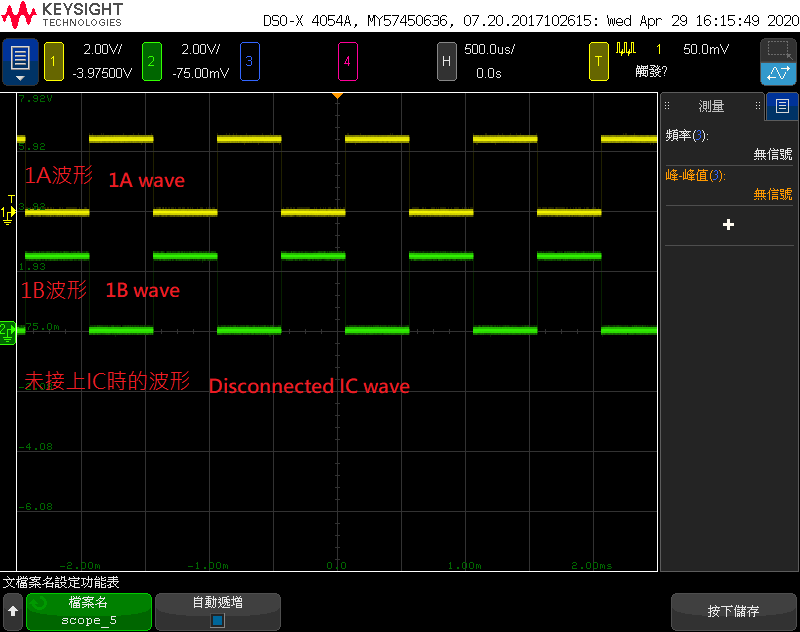
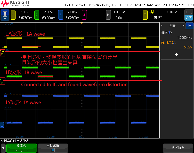
                  When I did not connect the IC, the measured A and / A square waves were normal, but after connecting the signal to the IC, I found that the waveform would be distorted (such as photos),      

                  What should I pay attention to?                       

               The output voltage is a 5Vcc square wave. Is there a recommended IC that can be converted to 3.3V and supplied to the MCU?

Note: There is a 100OHM resistor connected between lines 1A and 1B

                  N

  • Hello,

    This looks normal to me. The differential signal amplitude is just reduced due to the additional loading of the 100 Ohm termination resistance. The signal doesn't seem distorted in shape and is still of sufficient amplitude for the receiver to reliably determine its state (high or low).

    Is there a concern you have that I am missing?

    Regards,

    Max

  • The output voltage is a 5Vcc square wave. Is there a recommended IC that can be converted to 3.3V and supplied to the MCU?

  • I understand now.  The simplest solution would be to use a receiver IC whose VCC level can operate at 3.3 V.  If you needed 4 channels, a good choice would be AM26LV32E.  If you just need a single channel, THVD1450 or THVD1410 could be considered.  Or, if you wanted to keep the current transceiver a level shifting IC could be used to translate between the 5-V logic and 3.3-V logic.

    Regards,
    Max