Other Parts Discussed in Thread: TPS65982, TPS65988, TPS65987
Hi Team,
I'm following up on a question previously posted here: https://e2e.ti.com/support/interface/f/138/p/894307/3338967#3338967
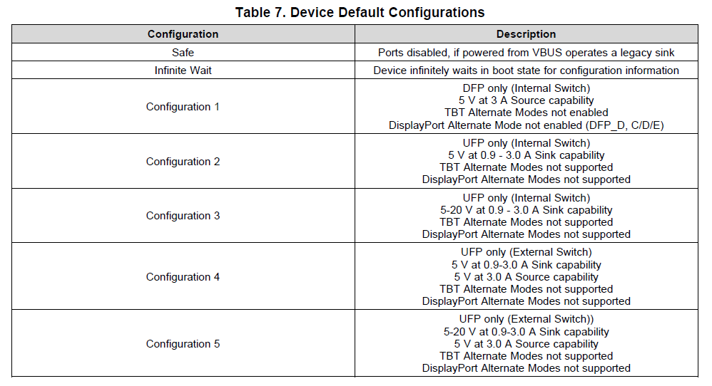
The question stated we're confused by is What is the default state of the GPIO pins individually GPIO0-21 of the TPS65987D when the device is running straight out of the box WITHOUT any additional configuration done through external Flash. The datasheet states that the "reset state" of the pins will by High Z inputs immediately after device power up, but what do the GPIOs stay in this state if they are not configured to do any other function and what happens is a signal is input into these pins? Do any other pins switch to a different primary function besides GPIO 5-7 for I2C and GPIO18-19 for USB D+/-?
Additionally, do we have any reference designs or schematics with the TPS65987D utilizing a high speed MUX? All of the ones I've seen online are only PD.
Regards,
Matt


