This thread has been locked.

If you have a related question, please click the "Ask a related question" button in the top right corner. The newly created question will be automatically linked to this question.

DS90UB953-Q1: Serialiser not recognising CSI-2 Frame Valid

Part Number: DS90UB953-Q1
Other Parts Discussed in Thread: TFP410

I have a system that connects to an Omnivision OV2740 image sensor through an FPD Link III serialiser (DS90UB953-Q1), retiimer (SN65DPHY440) and deserialiser (DS90QB960-Q1), the CSI-2 output from the deserialiser is further processed and displayed. The link works properly and images generated by the pattern generator in the serialiser are received without problems. However, when I put the serialiser in passthrough mode and try to display an image from the camera the serialiser doesn't recognise any start of frame packets. It's not possible to bring LV or FV out to a GPIO pin on the serialiser but it is possible to do this at the deserialiser where LV toggles with correct timing but FV remains high. The image sensor is programmed with proven manufacturer provided register values for 1080p at 60 Hz. The serialiser is set up for 2 lane CSI-2, synchronous mode (25 MHz from deserialiser) and provides a 24 MHz clock to the sensor. The Mode and General Status registers in the serialiser show no problems with either the forward or backward channels, the CSI status registers show:

CSI_ERR_COUNT 0x0000

CSI_ERR_STATUS 0x00

CSI_ERR_DLANE01 0x00

CSI_ERR_DLANE23 0x00

CSI_ERR_CLK_LANE 0x00

CSI_PKT_HDR_WC 0x0780

CSI_ECC 0x0B

The retimer CSR Register 0x0D shows no contention.

I've tried a number of register changes without success. Can anyone suggest what the problem might be ?

  • Hi David,

    I had some comments/suggestions below to better help with the issue. Can you provide your input.

    1) To clarify, what do you mean by passthrough mode? You mean when you don't use patgen and try to have the camera as the input source?

    2) So you bring out LV and FV on the des side and the LV looks good but FV is always high?

    3) Have you tried to connect the ser and des directly without the retimer? If so, what was the result? If not, can you please try to, so we can rule it out as an issue.

    4) Can you share the results of registers 0x4d, 0x4e, 0x58, 0x35, 0x6d, 0x7a on the 954 side.

    Regards,

    Mandeep Singh

  • Hello Mandeep,

    Thank you for picking this up.

    1) Yes, pattern generator off, camera enabled.

    2) Yes, that's correct.

    3) I haven't tried this, I'd have to remove the IC and wire across the tiny pads, can we leave this as a last resort ? The retimer is also a TI IC; does it have problems ? I haven't found an errata sheet for it.

    4) The design uses a DS90UB960 rather than a DS90UB954 but these registers seem much the same in both devices.

    Addr Data

    0x4d 0x53

    0x4e 0x0c

    0x58 0x4e

    0x35 0x01

    0x6d 0x78

    0x7a 0x0c

  • Hi David,

    Yes, we can leave it as a last resort and I'm not sure about the part itself. You would have to make a post in that specific forum as we deal with SerDes interfaces. I would certainly not wire the signal because of link degradation. Perhaps if you can get your hands on a 954/960 EVM, then you could use that as the Des.

    1) How are you measuring the FV? Are you triggering on the FV when you are doing the capture or triggering on the LV?

    2) Are you sure that FV is being pulled from RX PORT 1? It looks like you are using RX Port 1.

    3) 0x7A, 0x4d are showing some errors, can you read that register twice and see if the errors disappear? Those bits are clear on read and sometimes can be set during initialization. So read the register, wait about 10 seconds and read it again.

    Regards,

    Mandeep Singh

  • Hello Mandeep,

    1) The board has a test point connected to GPIO0 of the 960 so I can look at these signals one at a time by programming the GPIO0_PIN_CTL (0x10) register to output FV  from RX port 1 (set 0xC5) and to output LV from RX port 1 (set 0xE5). So in each case I'm triggering on the selected signal.

    2) I am using port 1 for testing, only this port is connected to a serialiser and this is the only port for which forwarding is enabled.

    3) I've run this test several times, each time the 960 is reset (DIGITAL_RESET1) and the software waits for this bit to self clear before going on to check that initialisation completes, REFCLK is valid, the correct revision ID is read and that the correct I/O voltage is detected before configuring the I2C and port control registers.

    When the image sensor is the source I see:

    Address    1st Read            2nd Read      Change

    0x4D         0x53                     0x43             Yes

    0x4E         0x0C / 0x4D         0x04             Yes

    0x58         0x4E                     0x4E

    0x35         0x01                     0x01

    0x6D         0x78                     0x78

    0x7A         0x02                     0x00             Yes

    When the serialiser pattern generator is the source I see:

    Address    1st Read    2nd Read      Change

    0x4D         0x53            0x43             Yes

    0x4E         0x45            0x04             Yes

    0x58         0x4E            0x4E

    0x35         0x01            0x01

    0x6D         0x78            0x78

    0x7A         0x00            0x00

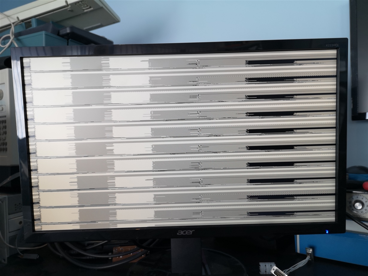
    Each time I run through the startup with the image sensor pattern generator as the source the system captures an initial corrupted image, see the attached, then nothing (because FV doesn't toggle).

  • Hi David,

    Can you set register 0x58 = 0x5E instead of x4E, this will ensure the BC is always ON and check if this changes anything. If this doesn't help, you may have to try connecting the imager directly to ensure the imager output is being captured properly with the processor.

    Regards,
    Mandeep Singh

  • Hello Mandeep,

    I've tried the change to the deserialiser BCC_CONFIG register and there is no change. I don't have an I2C problem; there are 3 ICs in addition to the image sensor that are slaves to the remote I2C master in the serialiser, I can communicate with all of them and I read back and check the chip ID from the image sensor during initialisation.

    I don't have any means to connect the image sensor directly to the MIPI decoder that is connected to the deserialiser output, i.e to remove the CSI-2 retimer. serialiser and deserialiser from the video path. I can try to remove the CSI-2 retimer and wire across its PCB pads so that the image sensor is directly connected to the serialiser. This will cause a small impedance discontinuity and extend the path that the image sensor has to drive which may cause other problems, but it may indicate if the problem is with the SN65DPHY440.

  • Hi David,

    I understand and I can see that doing the re-work itself may present you with issues of its own in terms of signal integrity. In terms of other options, we've already confirmed normal operation with Patgen on the serializer to the processor, so it does indicate that the retimer and SerDes are working with CSI data. If you want to further investigate the issue then an alternative approach might be to get a 960 EVM and connect that to the serializer and initialize the imager and capture the FV to see if it's still high. If it is still high, then I would conclude there's an issue with the initialization of the imager or the imager itself. If the FV is showing up as expected, then I would conclude that the retimer might be issue. Outside of this, If you have a different imager sensor that you can try initializing and capturing, that might be helpful as well to know if different imagers are displaying similar results. If they are, then I would look into the configuration of the imager and just ensure that there's nothing going wrong there with the registers being set on the imager. Beyond this, I don't see another option to try and debug your system. The issue needs to further isolated to see what's causing this but I hope these options provides some guidance.

    Regards,
    Mandeep Singh

  • Hello Mandeep,

    I've removed the CSI-2 retimer from between the image sensor and the serialiser and wired the signals across the SMD pads.This made no difference to the operation, i.e. an initial corrupted image arrives and then then FV is stuck high so the retimer isn't causing the problem. The system has four identical image sensor inputs and I see the same problem when I try another channel. I have contacted the OmniVision distributor in the UK and they have forwarded our sensor setup to OmniVision. The setup is copied from a sensor image demo' board although in that case the receiver is in an Intel FPGA.

  • Hi David,

    It makes sense because the was getting transmitted okay with patgen. You can try running the system exactly as they have it configured with the image sensor and intel FPGA and then try placing the SerDes in the path. I would also ask OV if there's a chance that the FV is transmitted as high from the imager. Otherwise, I provided a few recommendations in the last response, so let me know if you have any questions on those items.  

    Regards,
    Mandeep Singh

  • Hello Mandeep,

    Just to be clear; the path on the camera board is: image sensor -> CSI-2 retimer -> serialiser. The deserialiser is on the main board. I can receive pattern images from the deserialiser and the serialiser but haven't been able to correctly receive an image (pattern, or live) from the image sensor, i.e. through the retimer, which is why I tried bypassing the retimer.

  • David

         Let us check the clocking you are using. If you are using synch mode, then the Serializer is supposed to extract the clkock from the back channel. I am not sure how the clocking is being done witha retimer in between. A simple block diagram showing the data flow and the clocking for the overall system would help.

    Can you also check Line length and Line count on the 954 side ? )x73 and 0x74 and 0x75?

    Thanks

    Vijay

  • Hello Vijay,

    It looks like you've created a new response to my question, there's another thread here: e2e.ti.com/.../3364157. My initial post was a bit misleading, the retimer is a TI SN65DPHY440 CSI-2 retimer and so is between the image sensor and the 953 serialiser. The image path is: image sensor -> retimer -> 953 serialiser -> 960 deserialiser -> MIPI receiver in Lattice CrossLink FPGA -> isolating bus -> Xilinx FPGA -> TI TFP410 DVI driver. I can receive pattern images from the 953 serialiser so the FPD forward channel is working and I can access through I2C all of the camera board devices, including the image sensor, through the back channel. The I2C link to the image sensor connects to the serialiser, it's not routed through the retimer. I have tried removing and bypassing the retimer in case this was causing the problem but there was no change so I don't think that the retimer is causing a problem.

    The 960 has a 25 MHz clock and the SERDES devices are in synchronous mode. The 953 recovers the 25 MHz clock and its PLL generates a 24 MHz clock for the image sensor.

    In the 960 deserialiser the line count (combined 0x73 and 0x74) = 0x0000, the line length (combined 0x75 and 0x76) = 0x0000.

  • Hi David,

    Thanks for the clarification. While I understand you mentioned that the imager is good, there could be an issue with imager output into the SER. We can check if there's any errors or if packets are recieved by the SER. What is the value of registers 0x5c to 0x63 on the serializer side?

    Regards,
    Mandeep Singh

  • Hello Mandeep,

    I've made some changes to the registers of the image sensor and I now receive a correctly timed FV at the deserialiser. I've programmed the sensor to generate a pattern image and whilst this is stable it's a bit scrambled, however I doubt that this is caused by the SERDES link. I'm trying to get support from the sensor manufacturer.

  • Hello Mandeep,

    I've made some changes to the registers of the image sensor and I now receive a correctly timed FV at the deserialiser. I've programmed the sensor to generate a pattern image and whilst this is stable it's a bit scrambled, however I doubt that this is caused by the SERDES link. I'm trying to get support from the sensor manufacturer. The 960 deserialiser line count is now 1080 and the line length is 1920 which is correct.

    The serialiser register values are:

    Address             Data

    0x5C                    0

    0x5D                    0

    0x5E                    0

    0x5F                    0

    0x60                    0

    0x61                    0x2A

    0x62                    0x80

    0x63                    0x07

  • Hi David,

    That is great to hear. From the register results, it indicates there's no errors on the CSI data itself which further adds confidence to it being an issue with the configuration. It looks like you are now getting some of the expected results. Do you have any further questions regarding this topic?

    Regards,
    Mandeep Singh

  • Hello Mandeep,

    Not at the moment, thanks for your help.