This thread has been locked.

If you have a related question, please click the "Ask a related question" button in the top right corner. The newly created question will be automatically linked to this question.

SN75DP139: The DP to DVI cable which used SN75DP139 can not transfer image successfully

Part Number: SN75DP139

Hi Team ,

        My customer's DP to DVI cable which used SN75DP139 can not transfer image successfully . We found that :

        1. The cable can not transfer image successfully in the specific platform (Lenovo M720S、M720Q,Groplics UHD 630,Intel:,i7-8700,Windows10,Enterprise LTSC). But it can tranfer image successfully in other platform.

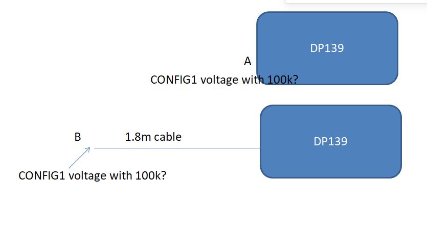
        2. The length of abnormal cable is 1.8m. And the cable can transfer image in the specific platnormally after shorting the length to 1m. 

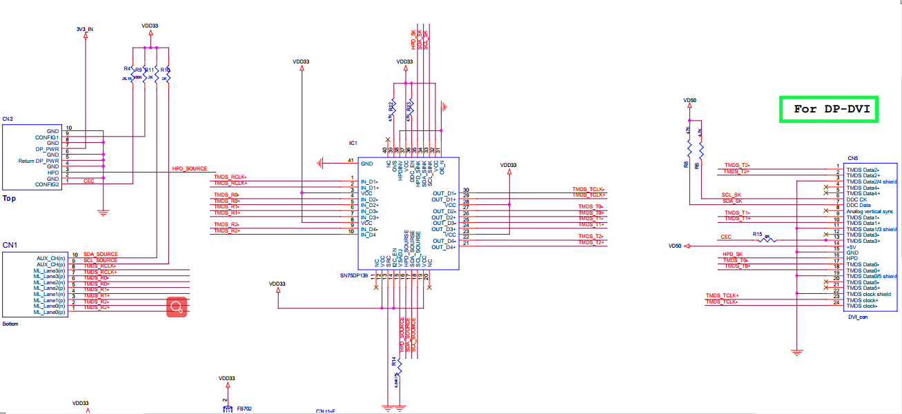
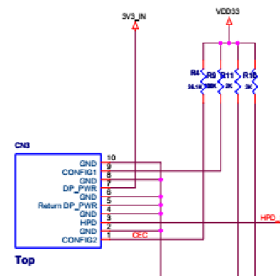
        The following picture is the schematic.We want to know why the issue will happens in specific platform.If it's a compatibility issue. Can TI offer the method to solve this issue ? Thank you! 


  • Hi,

    For DVI application, can you have I2C_EN pulled low? Have you tried different SRC and Vsadj settings?

    Thanks

    David

  • Hi David ,

              Yes . Have I2C_EN pulled low. I also have tried diffenert src and Vsadj settings . But the phenomenon is the same .

  • Can you change the DDC pullup on the DVI side from 4.7k to 2k? Any chance I can take a look at the board layout?

    Thanks

    David

  • Hi David ,

            Customser has done the test you suggested but nothing changed. I can send the pcb to you by E-mail for the confidentiality.

    Can you offer your E-mail address? Thank you!

  • Hi David,

    1, By customer's feedback, no used in modify DDC pull up resistor in DVI side.

    2. M720 will reboot during the failed connection.

    3.  In their test, they remove DDC pull up resistor in DP input side (R10/R11) and then the connection is succeed (has image in monitor)  with LV M720. But in this condition, no other desktop/pc can be worked at this condition.

     Any signal measurement we have to do to clear the issue?

    Regards,

    Gary Teng

  • Hi,

    I sent you a friendship request, please accept my request and then you can send the file to me.

    Thanks

    David

  • Gary

    Is this a compliant DVI cable? If a 1M cable works, but 1.8M does not work, the loss of the cable may be too large for these particular systems. But let's also take a look at the layout and if the layout can be improved.

    Do they have another different brand 1.8m cable they can test?

    Thanks

    David

  • Hi David ,

          The cable which length is 1.8m can also work normally besides the specific platform (Lenovo M720S、M720Q,Groplics UHD 630,Intel:,i7-8700,Windows10,Enterprise LTSC).

          Customer also tested the waveform between normals and failures and found there is a difference in the waveform of Clock_in.Please see the picture-1 and picture-2 . And customer thinks the "noise" looks more like crosstalk from Aux channel


                                                           Picture.1 Normals 


                                                                         Picture-2. Failures

           Base the "noise",customer tried to change the pull-up resistor to 4.3kΩ(The previous value is 100kΩ). And the cable (1.8m) can work normally .The picture-3 is the waveform .


                                                                                                          Picture.3


                                                                                                        Picture.4 modify

           But Config1 resistor should be 100K per standard. This is just an experiment to illustrate that the DDC can be improved by lowering the Config1 resistor value. It does not explain why the working cable can work without changing the Config1 resistor.

            So can TI continue to find out why to understand the root cause of the incompatibility issue? Thank you!

  • Can TI help to solve this issue ? Thank  you!

  • Hi,

    Looking at the layout, I don't see how the DDC could cause crosstalk on the CLOCK input since they are not routed next to each other on the board. I am concerned with the signal being routed on the bottom of the board as it appears that they are routed across broken plane. I am also concerned that when route from the top layer to the bottom layer, there is no GND via next to the signal via to provide a signal return path.

    I also don't understand how changing the CONFIG1 from 100k to 4.3k could fix the issue. If you change the resistor back from 4.3k to 100k, does the issue show up again?

    Also, for CN1, CN3, and CN5, where is the shield ground? CN1. CN3, and CN5 all look to be surface mounted connector. You would need a shield ground to provide mechanical stability.

    Thanks

    David

  • Hi David ,

           After communicating with customer . They do not think the issue is caused by layout for the product can workly normally in other computer except the platform (Lenovo M720S、M720Q,Groplics UHD 630,Intel:,i7-8700,Windows10,Enterprise LTSC). So can you explain why the issue will happen and why change the resistor to 4.3k can solve the issue ?  They are confused that why the 4.3k resistor can solve the issue and afraid that the change will cause other issue. Thank you! 

  • Hi.

    1. Is this repeatable? If you replace the 4.7k with 100k, are they seeing the failure again?

    2. If it is repeatable, can they measure the CONFIG1 voltage between a working platform and a failing platform? Changing from 100k to 4.7k is outside of the DP139 and should only impact the host operation, but not the DP139 operation.

    Thanks

    David 

  • Hi David ,

             It's repeatable. The Config1 voltage is the same in both working playform and failing playform. The voltage is 2V with 4.3k resistor and the other voltage is 0.783V with 100k resistior. Are there some risks if changing the resistor to 4.7k?

  • Hi,

    Thanks for the voltage measurement.

    Per the DP++ spec, the voltage on CONFIG1 needs to be above VIH for the cable adaptor to be recognized. The VIH is defined as MIN of 0.7*DP_PWR and MAX of DP_PWR_Max.

    If the voltage is 0.783V with a 100k resistor, then this voltage is below the VIH. The DP++ source will not recognize DP139 as a DP++ adaptor and outputs DP signal only. DP139 will not work with a DP signaling output. 

    A 4.7k is a stronger resistor comparing against the 100k resistor. I think you need to understand why the voltage is being pulled low with the 100k resistor with these particular failing platform.

    Thanks

    David


  • Hi David

    This is HPC Tech Inc, currently we are facing a crisis that our order has been postponed and soon will be canceled if we are not dealing the problem right now.

    We cannot afford to loss this order as 1kk/year, please we need your assistance to solve this issue.

    We have changed the resistor from 4.3k to 72k, and almost reach to 100k. The result shows it is workable. 

    Thus we would like your feedback regarding on this solution urgently. 

  • Hi,

    I have spoken to Gary Guo on this particular issue. This does look like a DP139 issue, it is an issue with these specific platforms that causing the CONFIG1 voltage to be below the VIH level. Please reach out to Gary for further discussion.

    Thanks

    David 

  • Hi David .

              Thank you for your great support . I have got connect with gary and will continue to solve the issue.

  • Hi David

    Thanks for your responds.

    There are more questions:

    1. For VIH value: 0.7V x 3.3V(DP Power) = 2.3V    <------ Is this how to calculate te VIH value?

    2. If above calculation is corrected, all of our test is not comply with this value. 

    for example: Dell(0.954V), 

    Please assist us on the calculation of VIH, since we have to issue the report to our customer, we need to state on our report!

    Thanks!

  • Hi,

    The Source device may discover the presence of a dual-mode cable adaptor by detecting CONFIG1 voltage level.
    • If the voltage on CONFIG1 is above VIH, the cable adaptor is plugged
    • If the voltage on CONFIG1 is below VIL, the cable adaptor is not plugged

    The VIH is defined as MIN of 0.7*DP_PWR and MAX of DP_PWR_Max. DP_PWR is 3.3V +/-10%, so your calculation is correct. 

    With 100k resistor, can you please measure the voltage at point A and B as shown below?

    Thanks

    David

  • HI David,

    Voltage measurement is Unchanged,

  • Hi,

    Can you measure the voltage with the DVI cable is removed but CN1 and CN3 connected?

    Can you also measure the voltage when DVI, CN1 and CN3 removes?

    Thanks

    David

  • HI David,

    Voltage measurement is Unchanged,

  • HI ,

    No voltage, no DVI plugged in
    no can't move CN1,CN3 ,is gold pin

    First of all, writing email back and forward takes awhile to make a question and answer.

    Is there a possible way to have a conference call with you? it is more faster and instant.

    1. Can we modify the resistor to 72k, and our customer wish to get approval from TI. If we can, how to modify the resistor?

  • Hi, 

    Please work through Gary Guo (local FAE) to schedule a conference call.

    The pullup resistor on CONFIG1 is outside of the DP139 implementation, I can't comment on the impact of using the 72k resistor. But from DP++ spec, the 72k is a violation of the spec.

    Thanks

    David