This thread has been locked.

If you have a related question, please click the "Ask a related question" button in the top right corner. The newly created question will be automatically linked to this question.

TCA4311A: Damaged devices

Part Number: TCA4311A
Other Parts Discussed in Thread: TCA9511A

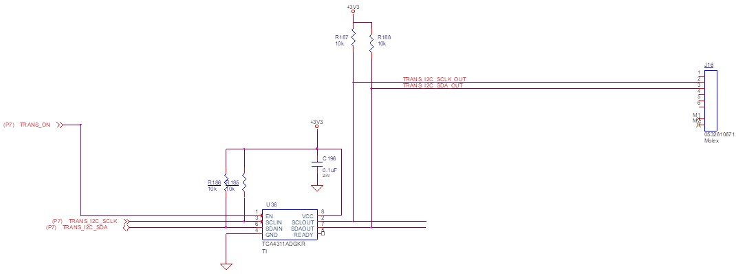
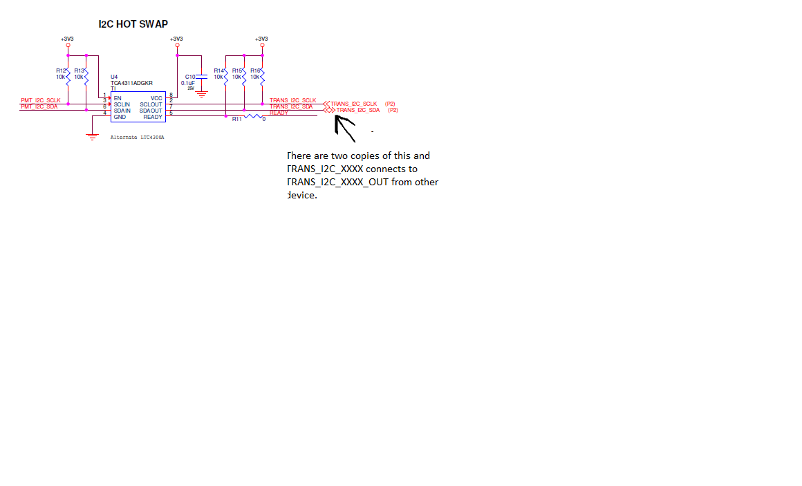
We have 3 TCA4311A devices connected.  One is on the Master board and two are on a different board.  All of the TCA4311A devices have the "OUT" pin connected.  The "IN pins go to the I2C devices on the other boards.  We have seen devices get damaged.  Figure 14 shows an implementation which has the "OUT" pin connected for a long trace.  Is it acceptable to have more than two connected this way?  We are trying to figure out why these devices are getting damaged.

  • Hey Bill,

    "We have seen devices get damaged."

    Did you see the devices were damaged after some use or they were broken upon power up?

    How many broken units are you seeing? (Are any successfully working?)

    How are you defining a device is damaged? (device no longer passes lows from out to in? Short to GND all the time on out pins? Rise time accelerators no longer activate? RDY signal never high?)

    Are you able to show a more indepth schematic for us to review? If you cannot share on an online forum, then we can review it offline. (you can email me at duynguyen@ti.com)

    "Figure 14 shows an implementation which has the "OUT" pin connected for a long trace."

    Figure 14 shows cable communication, are you using a long cable to communicate between boards? (how long?)

    Do you have o-scope shots of the communication on SDA/SCL of the cables?

    My initial guess is there is undershoot due to the parasitic cable inductance generating ringing when you drive low. This could break the device if it is going way below the absolute maximum value of -0.5V.We should be able to observe this on an o-scope shot

    "Is it acceptable to have more than two connected this way?"

    This should be okay though if the rise time accelerators and pull down occur at the same time, there may be some contention. If I recall correctly, there is a diode and a several hundreds of ohm resistance between the rise time accelerator and the in/out pins to restrict over current.

    -Bobby

  • Bobby,

    I have attached the following images:

    Tek00000 – failed chip unplugged

    Tek00001 – failed chip plugged in

    Tek00004 – working chip plugged in

    Tek00005 – working chip unplugged

    SCH1.png - TCA4311A on Master side.

    SCH2.png - One copy of TCA4311A connected to Master by cable.


  • Bill Adams1 said:

    Bobby,

    I have attached the following images:

    Tek00000 – failed chip unplugged

    Tek00001 – failed chip plugged in

    Tek00004 – working chip plugged in

    Tek00005 – working chip unplugged

    SCH1.png - TCA4311A on Master side.

    SCH2.png - One copy of TCA4311A connected to Master by cable.


    ^^From this waveform, it looks like the clock line has some kind of impedance divder which causes the idle voltage to rest below 3.3V. The spikes on the rising edge show that the rise time accelerator of this 4311A is working/not damaged on the clock. The data line looks like theres also a larger impedance divider which causes the signal to never rise above ~500mV so the rise time accelerator on this side likely doesn't activate.

    ^^With the device plugged it, the dataline looks like it is capable of triggering one of the rise time accelerators, this is likely due to the pull up resistors being in parallel allowing for a larger current (generating a higher idle voltage). The idle voltage on the clock line looks like its shifted up higher as well due to the additional current from the other pull up resistors so the spikes from the rise time accelerators are less noticeable.

    From the waveforms of the working boards, I don't see any undershoots that I was initially worried about so the damage likely isn't caused from the parasitic inductance. The schematic you provided looks okay to me as well.

    Are you able to provide any additional details on the previous questions I asked in my first post?


    Thanks,

    -Bobby

  • Bobby,

    Here are the answers to your other questions.

    Did you see the devices were damaged after some use or they were broken upon power up?

    After some use.

    How many broken units are you seeing? (Are any successfully working?)

    Working units stop functioning when this happens.

    How are you defining a device is damaged? (device no longer passes lows from out to in? Short to GND all the time on out pins? Rise time accelerators no longer activate? RDY signal never high?)

    See scope traces.

    Figure 14 shows cable communication, are you using a long cable to communicate between boards? (how long?)

    25.5" from the host to the first TCA4311A.  The signals are then sent to the other TCA4311A over an 18" cable.

    Do you have o-scope shots of the communication on SDA/SCL of the cables?

    Sent.

  • Hey Bill,

    Sorry for the delay in response here. It may be possible that the rise time accelerators are turning on at the same time on connected points and one device drives low after some delay. This may have a possibility of causing damage to the one who drives low while the other two are driving high with the rise time accelerators still on. Switching the device from TCA4311A to the TCA9511A may help since the algorithm for turning on and off the rise time accelerators are different and the rise time accelerators on the TCA9511A are also a bit weaker.

    -Bobby