This thread has been locked.

If you have a related question, please click the "Ask a related question" button in the top right corner. The newly created question will be automatically linked to this question.

DS26C31MQML: Failure mode and effect (Redundancy Structure)

Part Number: DS26C31MQML
Other Parts Discussed in Thread: AM26C31

Hi, I'm daejin

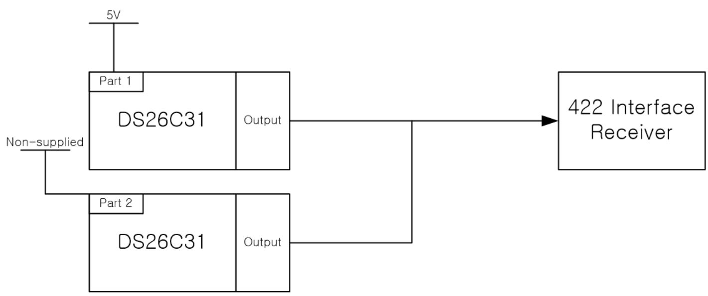
As seen in the related question, I configured the redundancy structure using 2ea DS26C31MQML.

When the primary channel driver is working, VCC power is not applied to the secondary channel.

Usually, the 422 communication is operated using the primary channel, and when there is a problem with 422 communication, are changed to the secondary channel. This means that the VCC of the primary channel is cut off and VCC is supplied to the secondary channel.

My question is:

If part failure occurs in the primary channel, how does it affect communication using the secondary channel?

I am curious about the typical part failure mode. Could you tell me the type of failure mode for this part?

I am concerned that the output pin is shorted to GND, internally.

If the part's output of the channel in use is shorted to GND internally, I think that both the primary and secondary channels cannot be operated for 422 communication even if it be changed to other channel.

Regards,

Daejin

  • Daejin,

    I think you're worried if the output is high impedance when the device is not powered. DS26C31MQML should behave this way. BTW, you could also consider AM26C31. On the first page of datasheet, this feature is stated. Please let me know if you have any more questions.

    Regards,

    Hao

  • Dear Hao,

    Thanks for answer

    The output pin of DS26C31 is retained high impedance when non-operate. It was confirmed using a multimeter.

    my question is type of failure mode of DS26C31.

    Can a failure mode actually occur? This means a case that the output pin of part is shorted to GND, internally. 
    If so, what is the probability?
    What is the main failure mode of DS26C31?
    Could you tell me the FIT or MTBF of the part?

    Thanks in advanced.

    Regards,

    Daejin

  • Daejin,

    The reliability data can be found on this TI website:

    www.ti.com/.../estimator.tsp

    You can use DS26C31 as the key word to find the proper package.

    Please be aware that the output pin shorting to GND is only one of the scenario of all failure. The FIT of this specific case should be smaller that the data you pull from the website.

    Please let me know if you have more questions.

    Regards,

    Hao

  • Dear Hao,

    Thanks for answer.

    I checked the FIT, MTBF value for this part.

    However, My concern is still the frequency of failure modes as I mentioned.

    I do not want quantitative values. just, based on your experience, is it a frequent failure mode? What are the frequent failure modes of this part?

    I have to decide if the redundant structure scheme that I designed is suitable.

    Thanks in advanced.

    Regards,

    Daejin.

  • Daejin,

    FIT is a statistic in time.

    www.ti.com/.../reliability-terminology.html

    FIT – Failures in Time, number of units failing per billion operating hours. You can use TI’s Reliability Estimator to get a FIT rate for most TI parts.

    failures in time equation

    Depending on the total units and operating hours, you can get an estimate of the failure parts. Please let me know if it makes sense to you.

    Regards,

    Hao

  • Dear Hao,

    Thanks for answer.

    I guess that the FIT value was calculated including a type of all failure mode for DS26C31.

    but, My concern is when output pin is shorting to GND.

    please, Could you tell me for the failure mode that I mentioned.

    also, second concern is main failure mode of DS26C31.

    I think that you had discovered the failure mode of the DS26C31 through many or long tests.

    What types of failure modes are frequently occurred?

    Example for failure mode;
    1. Any single output SC to VCC or GND
    2. Any single input SC to VCC or GND
    3. Differential out pin(+)" SC to Differential out pin(-)
    4. single input SC to GND
    5. VCC to GND SC
    6. OC of VCC

    OC means open circuit.
    SC means short circuit.

    Thank in advanced.

    Regards,

    Daejin.

  • Daejin,

    I agree the FIT could be pessimistic. However it might be hard to get the data for a specific failure condition. Let me see if I can find more data tuning toward your concern. BTW, what's the design goal?

    Regards,

    Hao

  • Hao,

    Thanks for answer.

    My design was described in more detail in support forums (Title : DS26C31MQML: Non-operating (no power supply), is the output pin of the part high impedance?)

    422 communication interface was designed as follows. This works fine.

    However, in terms of the failure mode, when one(Part 1) of the two drivers occurs failure mode, even if the driver channel was switched, the other part(Part 2) cannot be driven as well. When the type of failure mode is as same that my concern. ( the output pin cannot maintain high impedance when non-operating)

    Regards,

    Daejin.


  • Daejin,

    Thanks for the schematic. I understand your concern. However what I wanted to ask was the goal of the failure rate in the system. The total estimated failure is 3 FIT for this device, which means 3 failures per billion hours or 3 failures in 10k devices in 10 years (10 year life time is about 100k hours). As I checked, the specific output short mode is about 10% of the total failure, which includes the 1st and 3rd modes you listed. If all modes are considered, the total FIT should be used. Please let me know if you have any more questions.

    1. Any single output SC to VCC or GND
    2. Any single input SC to VCC or GND
    3. Differential out pin(+)" SC to Differential out pin(-)
    4. single input SC to GND
    5. VCC to GND SC
    6. OC of VCC

    Regards,

    Hao

  • Hao,

    Thanks for your active support.

    I understand your answer. 

    In terms of reliability, my design is fully met. but, If the probability of the failure mode that I am concerned had been high, I have tried to modify or reinforce my design. (this configuration is most important section in our application.) 

    In addition, could you tell me about the different types of failure modes and their probability?

    What is the failure mode with the highest probability?

    Thank in advanced.

    Daejin.

  • Daejin,

    Since it's a legacy device, we only have limited qual data. Roughly speaking (based on other similar devices), 40% fail is about the receiver, 50% about driver. However these failures are functional. The rest 10% includes short pins (any two pins) and stuck bus pins. I hope this information be helpful.

    Regards,

    Hao