This thread has been locked.

If you have a related question, please click the "Ask a related question" button in the top right corner. The newly created question will be automatically linked to this question.

TUSB542: TUSB542RWQR

Part Number: TUSB542

Dears,

Good morning.

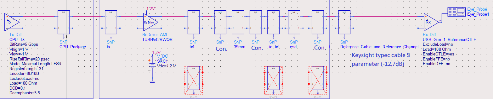
I have a question about the simulation of ADS with TI redriver IBIS ( TUSB542RWQR ).

I don't know what your DE and EQ defined description. Please give me a favor for this, thanks very much.

Q1:

If our EQ and DE setting by ADS were as below: (Our Pass Setting)

Tx1/Tx2: EQ: 0 (0dB by TI IBIS user guide); DE:3 (OS: 1100mV, DE: 0 dB by TI IBIS user guide)

Rx1/Rx2: EQ: 0 (0dB by TI IBIS user guide); DE:3 (OS: 1100mV, DE: 0 dB by TI IBIS user guide)

According to the above problem...how to design our DUT HW setting?

PS: HW setting defined as the table 2 of the Page13, refer to TUSB542 SLLSER3E –DECEMBER 2015–REVISED JUNE 2017.

Thanks very much.

  • Hi,

    I would use the following settings below. Adding additional DE on CH2 should not cause any issues as this TX faces the connector and typically has greater loss (i.e. USB cables) than CH1 TX.

    CNFG_A1 = High

    CNFG_B1 = Low

    CNFG_A2 = Low

    CNFG_B2 = Float

  • Hi,

    Thanks for your reply.

    Last a week,

    I have tried your DE/EQ setting, 

    CNFG_A1 = High

    CNFG_B1 = Low

    CNFG_A2 = Low

    CNFG_B2 = Float

    And our eye height was 109mV; eye width was 111ps, but followed the below setting, our eye height 146mV; eye width 122ps

    Tx1/Tx2: EQ: 0 (0dB by TI IBIS user guide); DE:3 (OS: 1100mV, DE: 0 dB by TI IBIS user guide)

    Rx1/Rx2: EQ: 0 (0dB by TI IBIS user guide); DE:3 (OS: 1100mV, DE: 0 dB by TI IBIS user guide)

    Do you have any idea for this case?

    Thanks very much.

  • There can be many difference between HW and simulation. Insertion loss, impedance profile and Host performance could be different between HW test and simulation which could explain the difference in result. What are the pre and post channels your are testing with in both setups?

  • Good morning.

    Okay, I agree with you completely. so, I will follow your suggestion. ( HW setting: CNFG_A1 = High, CNFG_B1 = Low, CNFG_A2 = Low, CNFG_B2 = Float )

    And I am sorry, I don't understand what "the pre/post channels" means...

    EH: 109mV; EW: 111ps and EH: 146mV; EW: 122ps <--- their setups?

    Thanks very much.

  • Hi,

    Pre/Post channel refers to the transmission media before and after the redriver. You can read more at the link below on this topic. 

    https://e2e.ti.com/support/interface/f/138/t/719929

    Yes, i was referring to your test setups in HW vs simulation. 

  • Good morning.

    Thanks, I got it.

    About the test setups, we just got the simulation result, didn't have EA test result.

    Therefore, they were the same setups by ADS.

    I just concern that our pass setting (as below) that can't implement on our HW.

    Tx1/Tx2: EQ: 0 (0dB by TI IBIS user guide); DE:3 (OS: 1100mV, DE: 0 dB by TI IBIS user guide)

    Rx1/Rx2: EQ: 0 (0dB by TI IBIS user guide); DE:3 (OS: 1100mV, DE: 0 dB by TI IBIS user guide)

    When we followed our setting, we got the low risk result by ADS. As the same setup that followed your suggestion, we got the high risk result by ADS.  

    Maybe we can look forward to the EA test result (followed your DE/EQ setting), too.

    And can learn more knowledge for EA and SI correlation. 

    Thanks.

  • Hi,

    I see now both results are from ADS. I do expect better performance on HW side with the settings provided. Could you describe (or share) your ADS test bench setup? What is your expected pre/post channel in the EA test case? I would like to understand what blocks your are using for your pre/post channel (i.e. S-parameters for PCB trace ect.). 

  • Good morning.

    HW Topology is as below: 

    ADS:

    Thanks.

  • Hi Cheymen,

    Keep in mind that you are only testing one direction of the device (AP to connector). The other path will have opposite pre/post channel (connector to AP), this is used to tune EQ_CON, DE_AP, OS_AP. Also it seems that the path in between the PCH and redriver is missing. Above image implies they are right next to each other. Please correct me if I am wrong.