This thread has been locked.

If you have a related question, please click the "Ask a related question" button in the top right corner. The newly created question will be automatically linked to this question.

SN65HVD75: Schematic review

Part Number: SN65HVD75
Other Parts Discussed in Thread: THVD1410, SN65HVD72

Hello TI Team,

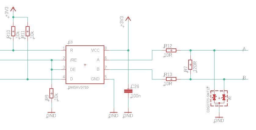
in a project we want to use two SN65HVD75 for a RS485 master and a RS485 slave (half duplex). Could you please review the implementation of the cuicuit? Basically, the circuit was implemented close to the data sheet.

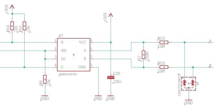
During further research, i noticed that designs were also implemented in which the order of series resistances and termination was changed. In front of the SN65HVD75 cames the termination resistor and then the series resistors. Here is my questions, which solution is the better way for the design?

Another question is about the bias for the RS485 master design. A pullup and a pulldown resistor are typically used for the A and B lines. Are these necessary when using the SN65HVD75? The question here is whether the bias resistors should be placed before or after the series resistors?

  • Hi Tony,

    We are reviewing this and will get back to you tomorrow.

    Max

  • Tony,

    The second schematic might be better than the first one from the signal integrity's point of view.

    The pull up/pull down are not necessary for SN65HVD75's application, since the fail-safe feature has been integrated in the device (Vit<0V). You can find more detail about the fail-safe setup in this app note.

    https://www.ti.com/lit/an/slyt324/slyt324.pdf

    However SN65HVD75 works with the pull up/pull down, whose preferred location is shown in the 3rd schematic.

    Regards,

    Hao

  • Hello Hao, thanks for your reply!

    i also think, that the second schematic is the better option. In an application report from TI i also found an comparison for the transceiver design. In this document the order is: transceiver, bias, series resistor and termination. With the fail-safe feature of the SN65HVD75, is the bus also working without any bias on the bus? Does the fail-safe feature makes a bias on the whole bus unnecessary? For example, when the other slaves have no fail-safe feature, will the fail-safe feature of the SN65HVD75 replaces a bias?

  • Tony,

    The pull up/down are used to generate a bias on bus. In this case, both the fail-safe and non-fail-safe devices will output a H in fault conditions.

    Without pull up/down, the fail-safe devices can still generate a H and the non-fail-safe devices cannot (undetermined).

    However the fail-safe devices don't create the bias on bus. If there were other non-fail-safe devices on the same bus, their output would still be undetermined in fault conditions.

    Regards,

    Hao

  • Hello Hao,

    thanks for your reply. For the RS485 Master interface with bias and termination i designed now the following schematic. In my opinion the 10 ohm series resistors should protect and limit the transceiver from higher current (transients). Therefore i put the series resistors in front of the transceiver near the bus to protect the LC filter and the transceiver. After the series resistors cames the LC filter and then the termination and bias. What do you think about this schematic? Is the dimension of the LC filter usefull? Would it be better to replace the ferrite pearls with a cm-choke?

    Another improvement would be to place three more capacitors between the ferrite beads and the series resistors, so that the design has C29/30/31 behind the ferrit pearls and the same before the ferrit pearls. In this case the signal is filtered over a RC filter with the 10 ohms resistors and followed by a LC filter. What do you think about this?

    Many thanks for your help!

  • Tony,

    I think it's more common to place the 10Ohm resistors behind the inductor. As you said, the resistors limit high transient current, which can be the last stage for protecting the IC. What's the model of the inductor? I'm not sure how much current could make the damage. BTW, what's the purpose of LC filter? 10nF looks a little high to high speed communication (I assume the data rate in your application is at least 10Mbps since you pick SN65HVD75). Another question is about the cable type and communication distance. If the termination needs to match the 120Ohm cable impedance, please be aware that the equivalent resistance is no longer 120Ohm with pull up/down resistors.

    Regards,

    Hao

  • Hello Hao,

    the inductor (ferrit bead) in the LC filter setup is used to filter high-frequency noise and very fast transients, which are too fast for the the TVS. The TVS should limit the high energy of esd transients. For the ferrit bead i didnt search for a specific model yet, but i think about a ferrit bead with a max. current specification of 2 ampere (continuous).

    The idea to place the 10Ohm resistors in front of the ferrit beads to the bus side was to generally limit the transient current of the whole lines and filters into the transceiver. When placing the series resistors behind the ferrit beads, as you said, then between the ferritand the capacitors or between the LC filter and the termination?

    In this application we work with 9600 baud. So, the 10nF might be okay, better would be to use 1nF or some pF for faster communication in other appllications.

    Regards,

    Tony

  • Tony,

    I appreciate your information. To be honest, it's hard to evaluate the system performance by looking at the schematic in this case. I think you need to run some experiments to see which method works the best. Also the design choice depends on what type of ESD events you want to protect from. One thing I noticed is that the behavior of the serial bus inductor is harder to predict than that of a resistor during some fast transient events. I don't see much difference between the two placements as long as the 10Ohm is behind the ferrit beads.

    If the data rate is 9600 baud, you may want to consider SN65HVD72 instead of SN65HVD75. We recommend choosing the proper rise/fall time based on the transmission speed. If you're interested, newly released THVD1410 works with the similar data rate with better ESD protection.

    Regards,

    Hao