This thread has been locked.

If you have a related question, please click the "Ask a related question" button in the top right corner. The newly created question will be automatically linked to this question.

TPS65988DJ: CC logic not work noramlly

Part Number: TPS65988DJ
Other Parts Discussed in Thread: TPS65987, TPS65988

I have used TPS65988DJ with titan ridge for a host design, I follow the intel CRB design with the reference firmware. But the PD chip not work normally as the CRB. When I plug the TBT device, there is no any response from the host. Though there are TBT bridge in the device manager.

I try to use other type C device, there still not any response from the device.

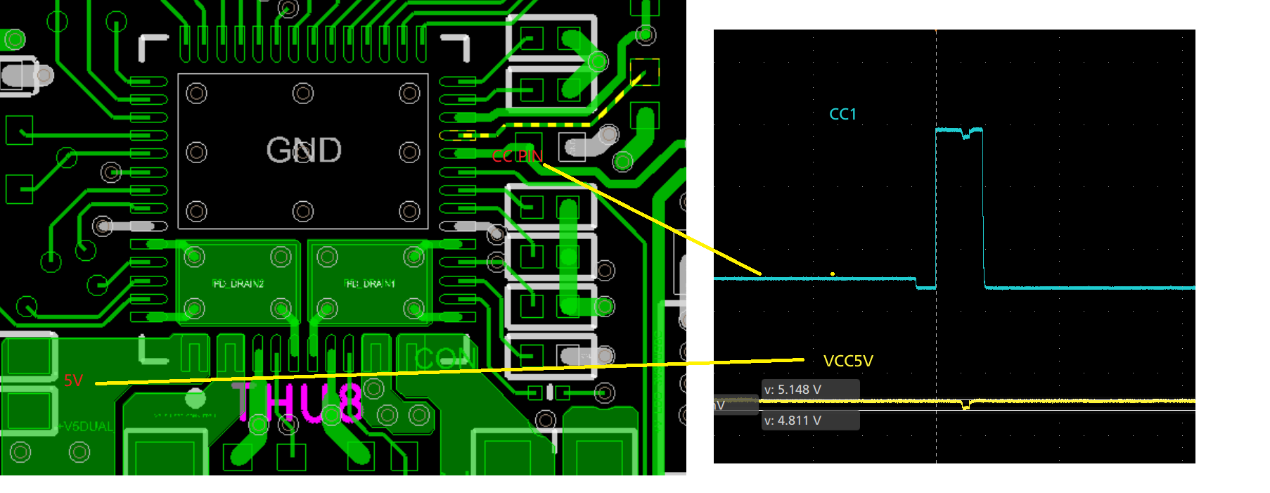
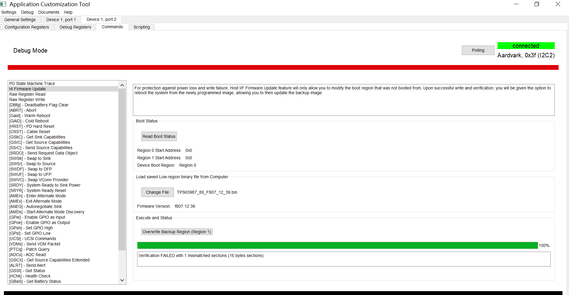
I check with TI “TPS65987_8_ACELITE_KRATOS Application Customization 6.2.8_RC2” GUI tool with Aardvark I2C tool to enter the debug mode, and it check the chip in the APP mode, and the PD state machine can sense the plug and unplug action, but the power path switches are off. So there is no power path to the VBUS, and check the CC logic, one pin is still communication, the other CC line is off, [low state] for CRB, the other line is 5V.

I have checked the hardware design with CRB, there seems no difference. So my question is , what should I check the hardware error which leads the abnormal behavior of the PD chip.


I have done another experiment, remove the TBT chip , only the PD chip left. The PD chip still not work normally.pf-cZ370-tbt.zip

  • i have checked the firmware version information: TPS65988 HW0030 FWF807.12.00 ZAce1

  • Hi,

    Thanks for reaching us. I'll get back to you by tomorrow. 

    Thanks
    Prajith 

  • Hi,

    Looks like no valid patch is running in the device. May I know the fw version that you are using and how you are downloading the patch to the PD Controller (via I2c or from spi flash). You can verify the FW version in debug mode. 

    Thanks

    Prajith

  • this is the  firmware version read from the device by the the GUI tool: HW0030 FWF807.12.00 ZAce1 [i2c 0x38]

    i have attched the waveform of the CC pin when plug type C devcie. 

    as you said, which debug register should i check? to know if the right patch is downloaded successfully.

    i have checked the layout witht he CRB, one different is the PP_cable pin, i add 0402 0 resistor on the power path, and the trace is a little slim, is that the cause of the fail CC communication? from the waveform, the CC can not boot to 5V normally. there is a drop in the 5V to the PD chip, i has added one bulk cap, but useless!

  • Hi, 

    Please test with the bin file attached. I hope you have an external SPI flash on the board to flash the patch bundle. You can refer the online training materials if you need any help on patch download using GUI - https://training.ti.com/tps6598x-application-customization-gui-tool-basic-introduction?context=1140344-1140206TPS65987_88_F807_12_39.zip

  • Prajith,

     thanks for your feedback, i have used the GUI tool update the patch code, but it seems failed please refer to the attached pic.

    I have checked the bin file i have used,it has the patch code in the low region.its version is F807_12_40, newer version than yours.i attached it too.TPS65987_88_F807_12_40_low region_full.zipcml-s-crb-tbt-titan ridge-tps65988dj-bkup-bin-20200413.zip

    I used the same bin on the intel comelake-s CRB, it works well. and my design leverage the intel CRB with the same bin, but it does not work normally.

    have you reviewed my design file? i think it probably hardware issue, not the firmware's problem, but i can not find the root cause.

  • Hi,

    I took a look at your design file and it looks good. The issue you are facing is associated with patch loading. First step should be verifying successful patch download to SPI flash and boot from SPI flash. Download default host template to SPI flash and monitor SPI lines to see if the PD controller reads patch bundle from the external SPI flash. Use GUI v6.2.7 and FW v39 for this experiment. If this experiment is not successful, please share the procedure that you follow to download the patch. 

    I hope 3.3V is available on VIN_3V3 rail when the device boot up. 

    Thanks

    Prajith 

  • Prajith , 

    I have done the spi erase and flash the rom from the binary->flash from current project,with the f807.12.40 base firmware. and after the flash with power shutdown and power on, i re-check the version register [0xF] in debug mode. the version is 0XF8071240. match new version. that is to say, it has been successsfully patch download right?

    i have spi data probe, can catch the date  PD chip read the SPI after power the PD chip. see attached file. spi session when power on.ziptop dxf.zip

    i have re-check the layout, and find the trace to PP_CABLE is 4mil, i am not sure if this will limit the current of the PP_cable from switching to CC line.

    when CC line communication, i can catch the voltage Drop on 5V to PD power pins. it is abnormal. could your help check the layout?i attached it.

  • Hi,

    "match new version. that is to say, it has been successsfully patch download right?" >>> Yes, its booting from the SPI flash. 

    PP_Cable pin is for supplying power to Vconn. To isolate the issue further you can try with a non-EMCA cable. When you say "when CC line communication, i can catch the voltage Drop on 5V to PD power pins." do you mean Vbus is dropping? Could you share PD trace ?

    Please note Vconn is not required for non-emca cable. Use non-EMCA cable for your tests if you are worried about the PP_Cable trace width.

    Thanks
    Prajith 

  • n i have tried the no-ecma cable, but still no vbus on my board. i attached the pd trace.please help check.  the test firmare is FW807.12.40.  and i have remove the TBT chip, and project setting the host is none.

    snapshot.zip i take snapshot for all configuration register for check.

    Port 1	Module 31	0x1ff = UNKNOWN
    Port 1	Type-C	0x10 = COMMON_STATE_UNATTACHED_SNK
    Port 1	Type-C	0x11 = COMMON_STATE_UNATTACHED_SRC
    Port 1	Type-C	0x10 = COMMON_STATE_UNATTACHED_SNK
    Port 1	Type-C	0x11 = COMMON_STATE_UNATTACHED_SRC
    Port 1	Type-C	0x10 = COMMON_STATE_UNATTACHED_SNK
    Port 0	Type-C	0xa = COMMON_STATE_ATTACHED_SRC
    Port 0	BC 1.2	0xd = CHARGER_DETECTION_DISABLED
    Port 0	INT	0x19 = DATA_STATUS_UPDATE
    Port 0	INT	0x3 = PLUG_INSERT_OR_REMOVAL
    Port 0	PD	0x2 = PEState_LaunchPolicyEngine
    Port 0	PD	0x2e = PEState_Enable_VCONN
    Port 0	PD	0x2f = PEState_Enable_VBUS
    Port 0	BC 1.2	0x4 = CHARGER_DETECTION_COMPLETE
    Port 0	Module 7	0x11 = UNKNOWN
    Port 0	INT	0x19 = DATA_STATUS_UPDATE
    Port 0	PD	0xbf = PEState_ErrorRecovery
    Port 0	PD	0x1 = PEState_CableTypeDetect
    Port 0	INT	0x3 = PLUG_INSERT_OR_REMOVAL
    Port 0	INT	0x19 = DATA_STATUS_UPDATE
    Port 0	Type-C	0x1 = SRC_STATE_ERROR_RECOVERY
    Port 0	VBUS	0xcc = VBUSState_MON_HILO
    Port 0	VBUS	0x91 = VBUSState_MON_LO
    Port 0	VBUS	0x90 = VBUSState_MON_HI
    Port 1	Type-C	0x11 = COMMON_STATE_UNATTACHED_SRC
    Port 1	Type-C	0x10 = COMMON_STATE_UNATTACHED_SNK
    Port 1	Type-C	0x11 = COMMON_STATE_UNATTACHED_SRC
    Port 1	Type-C	0x10 = COMMON_STATE_UNATTACHED_SNK
    Port 1	Type-C	0x11 = COMMON_STATE_UNATTACHED_SRC
    Port 1	Type-C	0x10 = COMMON_STATE_UNATTACHED_SNK
    Port 0	Type-C	0x10 = COMMON_STATE_UNATTACHED_SNK
    Port 1	Type-C	0x11 = COMMON_STATE_UNATTACHED_SRC
    Port 0	Type-C	0x11 = COMMON_STATE_UNATTACHED_SRC
    Port 0	Type-C	0xe = COMMON_STATE_ATTACHWAIT_SRC
    Port 1	Type-C	0x10 = COMMON_STATE_UNATTACHED_SNK
    Port 1	Type-C	0x11 = COMMON_STATE_UNATTACHED_SRC
    Port 1	Type-C	0x10 = COMMON_STATE_UNATTACHED_SNK
    Port 1	Type-C	0x11 = COMMON_STATE_UNATTACHED_SRC
    Port 1	Type-C	0x10 = COMMON_STATE_UNATTACHED_SNK
    Port 0	Type-C	0xa = COMMON_STATE_ATTACHED_SRC
    Port 0	BC 1.2	0xd = CHARGER_DETECTION_DISABLED
    Port 0	INT	0x19 = DATA_STATUS_UPDATE
    Port 0	INT	0x3 = PLUG_INSERT_OR_REMOVAL
    Port 0	PD	0x2 = PEState_LaunchPolicyEngine
    Port 0	PD	0x2e = PEState_Enable_VCONN
    Port 0	PD	0x2f = PEState_Enable_VBUS
    Port 0	BC 1.2	0x4 = CHARGER_DETECTION_COMPLETE
    Port 0	Module 7	0x11 = UNKNOWN
    Port 0	INT	0x19 = DATA_STATUS_UPDATE
    Port 0	PD	0xbf = PEState_ErrorRecovery
    Port 0	PD	0x1 = PEState_CableTypeDetect
    Port 0	INT	0x3 = PLUG_INSERT_OR_REMOVAL
    Port 0	INT	0x19 = DATA_STATUS_UPDATE
    Port 0	Type-C	0x1 = SRC_STATE_ERROR_RECOVERY
    Port 0	VBUS	0xcc = VBUSState_MON_HILO
    Port 0	VBUS	0x91 = VBUSState_MON_LO
    Port 0	VBUS	0x90 = VBUSState_MON_HI
    Port 1	Type-C	0x11 = COMMON_STATE_UNATTACHED_SRC
    Port 1	Type-C	0x10 = COMMON_STATE_UNATTACHED_SNK
    Port 1	Type-C	0x11 = COMMON_STATE_UNATTACHED_SRC
    Port 1	Type-C	0x10 = COMMON_STATE_UNATTACHED_SNK
    Port 1	Type-C	0x11 = COMMON_STATE_UNATTACHED_SRC
    Port 1	Type-C	0x10 = COMMON_STATE_UNATTACHED_SNK
    Port 0	Type-C	0x10 = COMMON_STATE_UNATTACHED_SNK
    Port 1	Type-C	0x11 = COMMON_STATE_UNATTACHED_SRC
    Port 0	Type-C	0x11 = COMMON_STATE_UNATTACHED_SRC
    Port 0	Type-C	0xe = COMMON_STATE_ATTACHWAIT_SRC
    Port 1	Type-C	0x10 = COMMON_STATE_UNATTACHED_SNK
    Port 1	Type-C	0x11 = COMMON_STATE_UNATTACHED_SRC
    Port 1	Type-C	0x10 = COMMON_STATE_UNATTACHED_SNK
    Port 1	Type-C	0x11 = COMMON_STATE_UNATTACHED_SRC
    Port 0	Type-C	0xa = COMMON_STATE_ATTACHED_SRC
    Port 0	BC 1.2	0xd = CHARGER_DETECTION_DISABLED
    Port 0	INT	0x19 = DATA_STATUS_UPDATE
    Port 0	INT	0x3 = PLUG_INSERT_OR_REMOVAL
    Port 0	PD	0x2 = PEState_LaunchPolicyEngine
    Port 0	PD	0x2e = PEState_Enable_VCONN
    Port 0	PD	0x2f = PEState_Enable_VBUS
    Port 0	BC 1.2	0x4 = CHARGER_DETECTION_COMPLETE
    Port 0	Module 7	0x11 = UNKNOWN
    Port 0	INT	0x19 = DATA_STATUS_UPDATE
    Port 0	PD	0xbf = PEState_ErrorRecovery
    Port 0	PD	0x1 = PEState_CableTypeDetect
    Port 0	INT	0x3 = PLUG_INSERT_OR_REMOVAL
    Port 0	INT	0x19 = DATA_STATUS_UPDATE
    Port 0	Type-C	0x1 = SRC_STATE_ERROR_RECOVERY
    Port 0	VBUS	0xcc = VBUSState_MON_HILO
    Port 0	VBUS	0x91 = VBUSState_MON_LO
    Port 0	VBUS	0x90 = VBUSState_MON_HI
    Port 1	Type-C	0x10 = COMMON_STATE_UNATTACHED_SNK
    Port 1	Type-C	0x11 = COMMON_STATE_UNATTACHED_SRC
    Port 1	Type-C	0x10 = COMMON_STATE_UNATTACHED_SNK
    Port 1	Type-C	0x11 = COMMON_STATE_UNATTACHED_SRC
    Port 1	Type-C	0x10 = COMMON_STATE_UNATTACHED_SNK
    Port 1	Type-C	0x11 = COMMON_STATE_UNATTACHED_SRC
    Port 0	Type-C	0x10 = COMMON_STATE_UNATTACHED_SNK
    Port 1	Type-C	0x10 = COMMON_STATE_UNATTACHED_SNK
    Port 0	Type-C	0x11 = COMMON_STATE_UNATTACHED_SRC
    Port 0	Type-C	0xe = COMMON_STATE_ATTACHWAIT_SRC
    Port 1	Type-C	0x11 = COMMON_STATE_UNATTACHED_SRC
    Port 1	Type-C	0x10 = COMMON_STATE_UNATTACHED_SNK
    Port 1	Type-C	0x11 = COMMON_STATE_UNATTACHED_SRC
    Port 1	Type-C	0x10 = COMMON_STATE_UNATTACHED_SNK
    Port 0	Type-C	0xa = COMMON_STATE_ATTACHED_SRC
    Port 0	BC 1.2	0xd = CHARGER_DETECTION_DISABLED
    Port 0	INT	0x19 = DATA_STATUS_UPDATE
    Port 0	INT	0x3 = PLUG_INSERT_OR_REMOVAL
    Port 0	PD	0x2 = PEState_LaunchPolicyEngine
    Port 0	PD	0x2e = PEState_Enable_VCONN
    Port 0	PD	0x2f = PEState_Enable_VBUS
    Port 0	BC 1.2	0x4 = CHARGER_DETECTION_COMPLETE
    Port 0	Module 7	0x11 = UNKNOWN
    Port 0	INT	0x19 = DATA_STATUS_UPDATE
    Port 0	PD	0xbf = PEState_ErrorRecovery
    Port 1	Type-C	0x11 = COMMON_STATE_UNATTACHED_SRC
    Port 0	PD	0x1 = PEState_CableTypeDetect
    Port 0	INT	0x3 = PLUG_INSERT_OR_REMOVAL
    Port 0	INT	0x19 = DATA_STATUS_UPDATE
    Port 0	Type-C	0x1 = SRC_STATE_ERROR_RECOVERY
    Port 0	VBUS	0xcc = VBUSState_MON_HILO
    Port 0	VBUS	0x91 = VBUSState_MON_LO
    Port 0	VBUS	0x90 = VBUSState_MON_HI
    Port 1	Type-C	0x10 = COMMON_STATE_UNATTACHED_SNK
    Port 1	Type-C	0x11 = COMMON_STATE_UNATTACHED_SRC
    Port 1	Type-C	0x10 = COMMON_STATE_UNATTACHED_SNK
    Port 1	Type-C	0x11 = COMMON_STATE_UNATTACHED_SRC
    Port 1	Type-C	0x10 = COMMON_STATE_UNATTACHED_SNK
    Port 1	Type-C	0x11 = COMMON_STATE_UNATTACHED_SRC
    Port 0	Type-C	0x10 = COMMON_STATE_UNATTACHED_SNK
    Port 1	Type-C	0x10 = COMMON_STATE_UNATTACHED_SNK
    Port 0	Type-C	0x11 = COMMON_STATE_UNATTACHED_SRC
    Port 0	Type-C	0xe = COMMON_STATE_ATTACHWAIT_SRC
    Port 1	Type-C	0x11 = COMMON_STATE_UNATTACHED_SRC
    Port 1	Type-C	0x10 = COMMON_STATE_UNATTACHED_SNK
    Port 1	Type-C	0x11 = COMMON_STATE_UNATTACHED_SRC
    Port 0	Type-C	0xa = COMMON_STATE_ATTACHED_SRC
    Port 0	BC 1.2	0xd = CHARGER_DETECTION_DISABLED
    Port 0	INT	0x19 = DATA_STATUS_UPDATE
    Port 0	INT	0x3 = PLUG_INSERT_OR_REMOVAL
    Port 0	PD	0x2 = PEState_LaunchPolicyEngine
    Port 0	PD	0x2e = PEState_Enable_VCONN
    Port 0	PD	0x2f = PEState_Enable_VBUS
    Port 0	BC 1.2	0x4 = CHARGER_DETECTION_COMPLETE
    Port 0	Module 7	0x11 = UNKNOWN
    Port 0	INT	0x19 = DATA_STATUS_UPDATE
    Port 0	PD	0xbf = PEState_ErrorRecovery
    Port 0	PD	0x1 = PEState_CableTypeDetect
    Port 0	INT	0x3 = PLUG_INSERT_OR_REMOVAL
    Port 0	INT	0x19 = DATA_STATUS_UPDATE
    Port 0	Type-C	0x1 = SRC_STATE_ERROR_RECOVERY
    Port 0	VBUS	0xcc = VBUSState_MON_HILO
    Port 0	VBUS	0x91 = VBUSState_MON_LO
    Port 0	VBUS	0x90 = VBUSState_MON_HI
    Port 1	Type-C	0x10 = COMMON_STATE_UNATTACHED_SNK
    Port 1	Type-C	0x11 = COMMON_STATE_UNATTACHED_SRC
    Port 1	Type-C	0x10 = COMMON_STATE_UNATTACHED_SNK
    Port 1	Type-C	0x11 = COMMON_STATE_UNATTACHED_SRC
    Port 1	Type-C	0x10 = COMMON_STATE_UNATTACHED_SNK
    Port 1	Type-C	0x11 = COMMON_STATE_UNATTACHED_SRC
    Port 1	Type-C	0x10 = COMMON_STATE_UNATTACHED_SNK
    Port 0	Type-C	0x10 = COMMON_STATE_UNATTACHED_SNK
    Port 1	Type-C	0x11 = COMMON_STATE_UNATTACHED_SRC
    Port 1	Type-C	0x10 = COMMON_STATE_UNATTACHED_SNK
    Port 0	Type-C	0x11 = COMMON_STATE_UNATTACHED_SRC
    Port 0	Type-C	0xe = COMMON_STATE_ATTACHWAIT_SRC
    Port 1	Type-C	0x11 = COMMON_STATE_UNATTACHED_SRC
    Port 1	Type-C	0x10 = COMMON_STATE_UNATTACHED_SNK
    Port 1	Type-C	0x11 = COMMON_STATE_UNATTACHED_SRC
    Port 1	Type-C	0x10 = COMMON_STATE_UNATTACHED_SNK
    Port 0	Type-C	0xa = COMMON_STATE_ATTACHED_SRC
    Port 0	BC 1.2	0xd = CHARGER_DETECTION_DISABLED
    Port 0	INT	0x19 = DATA_STATUS_UPDATE
    Port 0	INT	0x3 = PLUG_INSERT_OR_REMOVAL
    Port 0	PD	0x2 = PEState_LaunchPolicyEngine
    Port 0	PD	0x2e = PEState_Enable_VCONN
    Port 0	PD	0x2f = PEState_Enable_VBUS
    Port 0	BC 1.2	0x4 = CHARGER_DETECTION_COMPLETE
    Port 0	Module 7	0x11 = UNKNOWN
    Port 0	INT	0x19 = DATA_STATUS_UPDATE
    Port 0	PD	0xbf = PEState_ErrorRecovery
    Port 0	PD	0x1 = PEState_CableTypeDetect
    Port 0	INT	0x3 = PLUG_INSERT_OR_REMOVAL
    Port 0	INT	0x19 = DATA_STATUS_UPDATE
    Port 0	Type-C	0x1 = SRC_STATE_ERROR_RECOVERY
    Port 0	VBUS	0xcc = VBUSState_MON_HILO
    Port 0	VBUS	0x91 = VBUSState_MON_LO
    Port 0	VBUS	0x90 = VBUSState_MON_HI
    Port 1	Type-C	0x11 = COMMON_STATE_UNATTACHED_SRC
    Port 1	Type-C	0x10 = COMMON_STATE_UNATTACHED_SNK
    Port 1	Type-C	0x11 = COMMON_STATE_UNATTACHED_SRC
    Port 1	Type-C	0x10 = COMMON_STATE_UNATTACHED_SNK
    Port 1	Type-C	0x11 = COMMON_STATE_UNATTACHED_SRC
    Port 1	Type-C	0x10 = COMMON_STATE_UNATTACHED_SNK
    Port 0	Type-C	0x10 = COMMON_STATE_UNATTACHED_SNK
    Port 1	Type-C	0x11 = COMMON_STATE_UNATTACHED_SRC
    Port 0	Type-C	0x11 = COMMON_STATE_UNATTACHED_SRC
    Port 0	Type-C	0xe = COMMON_STATE_ATTACHWAIT_SRC
    Port 1	Type-C	0x10 = COMMON_STATE_UNATTACHED_SNK
    Port 1	Type-C	0x11 = COMMON_STATE_UNATTACHED_SRC
    Port 1	Type-C	0x10 = COMMON_STATE_UNATTACHED_SNK
    Port 1	Type-C	0x11 = COMMON_STATE_UNATTACHED_SRC
    Port 1	Type-C	0x10 = COMMON_STATE_UNATTACHED_SNK
    Port 0	Type-C	0xa = COMMON_STATE_ATTACHED_SRC
    Port 0	BC 1.2	0xd = CHARGER_DETECTION_DISABLED
    Port 0	INT	0x19 = DATA_STATUS_UPDATE
    Port 0	INT	0x3 = PLUG_INSERT_OR_REMOVAL
    Port 0	PD	0x2 = PEState_LaunchPolicyEngine
    Port 0	PD	0x2e = PEState_Enable_VCONN
    Port 0	PD	0x2f = PEState_Enable_VBUS
    Port 0	BC 1.2	0x4 = CHARGER_DETECTION_COMPLETE
    Port 0	Module 7	0x11 = UNKNOWN
    Port 0	INT	0x19 = DATA_STATUS_UPDATE
    Port 0	PD	0xbf = PEState_ErrorRecovery
    Port 0	PD	0x1 = PEState_CableTypeDetect
    Port 0	INT	0x3 = PLUG_INSERT_OR_REMOVAL
    Port 0	INT	0x19 = DATA_STATUS_UPDATE
    Port 0	Type-C	0x1 = SRC_STATE_ERROR_RECOVERY
    Port 0	VBUS	0xcc = VBUSState_MON_HILO
    Port 0	VBUS	0x91 = VBUSState_MON_LO
    Port 0	VBUS	0x90 = VBUSState_MON_HI
    Port 1	Type-C	0x11 = COMMON_STATE_UNATTACHED_SRC
    Port 1	Type-C	0x10 = COMMON_STATE_UNATTACHED_SNK
    Port 1	Type-C	0x11 = COMMON_STATE_UNATTACHED_SRC
    Port 1	Type-C	0x10 = COMMON_STATE_UNATTACHED_SNK
    Port 1	Type-C	0x11 = COMMON_STATE_UNATTACHED_SRC
    Port 0	Type-C	0x10 = COMMON_STATE_UNATTACHED_SNK
    Port 1	Type-C	0x10 = COMMON_STATE_UNATTACHED_SNK
    Port 1	Type-C	0x11 = COMMON_STATE_UNATTACHED_SRC
    Port 0	Type-C	0x11 = COMMON_STATE_UNATTACHED_SRC
    Port 0	Type-C	0xe = COMMON_STATE_ATTACHWAIT_SRC
    Port 1	Type-C	0x10 = COMMON_STATE_UNATTACHED_SNK
    Port 1	Type-C	0x11 = COMMON_STATE_UNATTACHED_SRC
    Port 1	Type-C	0x10 = COMMON_STATE_UNATTACHED_SNK
    Port 1	Type-C	0x11 = COMMON_STATE_UNATTACHED_SRC
    Port 0	Type-C	0xa = COMMON_STATE_ATTACHED_SRC
    Port 0	BC 1.2	0xd = CHARGER_DETECTION_DISABLED
    Port 0	INT	0x19 = DATA_STATUS_UPDATE
    Port 0	INT	0x3 = PLUG_INSERT_OR_REMOVAL
    Port 0	PD	0x2 = PEState_LaunchPolicyEngine
    Port 0	PD	0x2e = PEState_Enable_VCONN
    Port 0	PD	0x2f = PEState_Enable_VBUS
    Port 0	BC 1.2	0x4 = CHARGER_DETECTION_COMPLETE
    Port 0	Module 7	0x11 = UNKNOWN
    Port 0	INT	0x19 = DATA_STATUS_UPDATE
    Port 0	PD	0xbf = PEState_ErrorRecovery
    Port 0	PD	0x1 = PEState_CableTypeDetect
    Port 0	INT	0x3 = PLUG_INSERT_OR_REMOVAL
    Port 0	INT	0x19 = DATA_STATUS_UPDATE
    Port 0	Type-C	0x1 = SRC_STATE_ERROR_RECOVERY
    Port 0	VBUS	0xcc = VBUSState_MON_HILO
    Port 0	VBUS	0x91 = VBUSState_MON_LO
    Port 0	VBUS	0x90 = VBUSState_MON_HI
    Port 1	Type-C	0x10 = COMMON_STATE_UNATTACHED_SNK
    Port 1	Type-C	0x11 = COMMON_STATE_UNATTACHED_SRC
    Port 1	Type-C	0x10 = COMMON_STATE_UNATTACHED_SNK
    Port 1	Type-C	0x11 = COMMON_STATE_UNATTACHED_SRC

  • Hi,

    Could you connect 5K resistor b/w CC and Ground on your board? I expect 5V on the Vbus. Please let me know the test result. 

    One more thing, please fill some value in the customer use field and check whether you are seeing the same value in debug mode. This is to check whether Patch configuration is getting loaded correctly. 

    Thanks
    Prajith

  •  the root cause for the vbus not work is found, it is the vbus schottky diode ,which is reverse assemblied, which leads to vbus forward to GND.

    still thanks for your feedback!

  • Hello,

    Glad to know that the issue is solved.

    Thanks
    Prajith