Part Number: DP83867ERGZ-S-EVM
Other Parts Discussed in Thread: USB-2-MDIO, DP83867E, DP83867IS, DP83867CS, DP83867CR, DP83867IR
Hello,
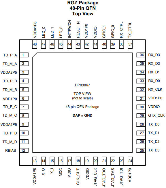
I would like to deactivate auto-negotiation using the "RX CTRL" pin of the DP83867ERGZ component.

When I activate auto-negotiation by the "Rx_CTRL" in mode 3, the ethernet link is created with the computer
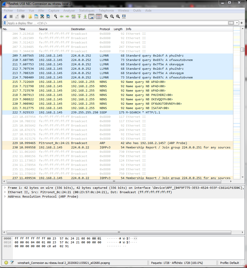
When I modify the "Rx_CTRL" pin in mode 4 to deactivate auto-negotiation. I cannot find an Ethernet link with a computer configured (see "Config computer" in attachment) :
- Speed : 1000Mbps
- Direction : Full-Duplex
- Auto-negotiation : OFF

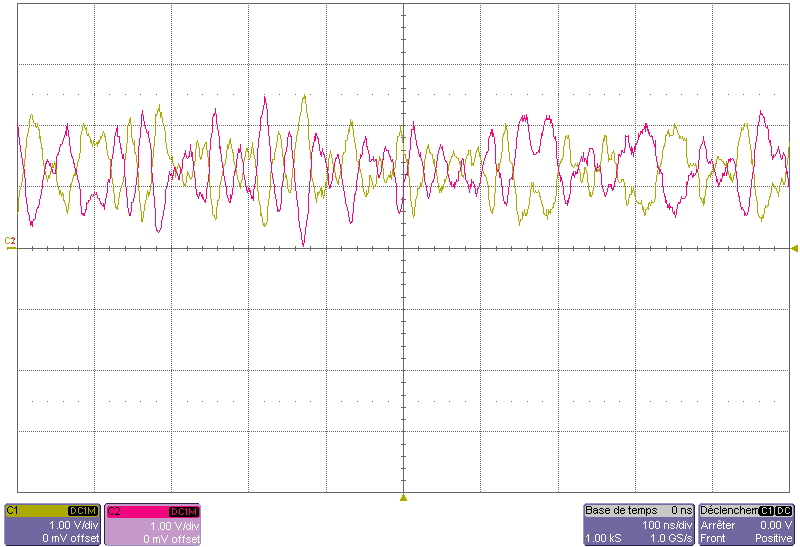
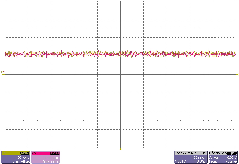
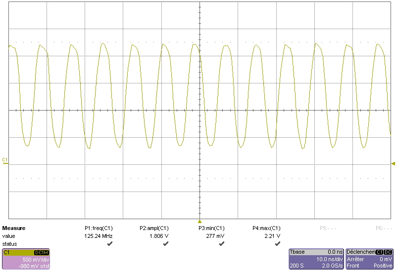
However, the "Rx_CLK" pin oscillates at 125Mhz which indicates a 1000-Mbps Mode
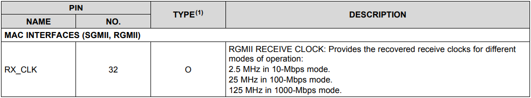
Measurement of pin "Rx_CLK" when auto-negotiation is disabled (Mode 4) by pin "Rx_CTRL"
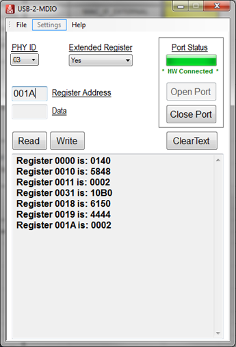
The state of the registers when the computer is connected with un RJ45 Cable
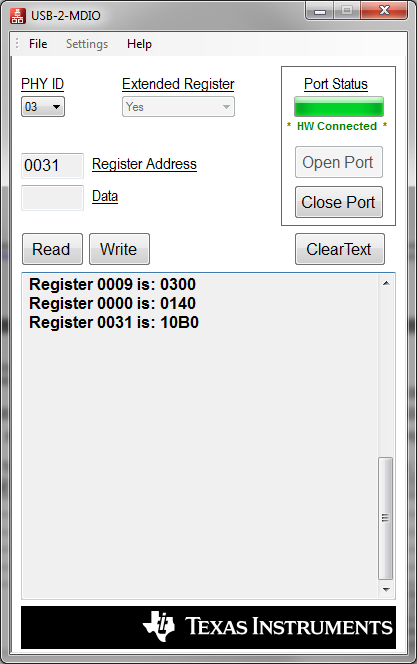
Register 0000 is: 0140
bit 6 - SPEED SELECTION MSB Value by default -> 1, RW Comment -> Speed Select: See description for bit 13.
bit 6 - SPEED SELECTION MSB Value by default -> 1, RW Comment -> Speed Select: See description for bit 13.
Speed Select (Bits 6, 13):
When auto-negotiation is disabled writing to this bit allows the port speed to be selected.
10 = 1000 Mbps
bit 8 - DUPLEX MODE Value by default -> Strap, RW Comment -> Duplex Mode:
When auto-negotiation is disabled writing to this bit allows the port Duplex capability to be selected
1 = Full Duplex operation.
Register 0031 is: 10B0
bit 12 and 4 are reserve
bit 12 and 4 are reserve
bit 6:5 - SGMII_AUTONEG_TIMER Value by default -> 01, RW Comment -> SGMII Auto-Negotiation Timer Duration:
01: 2 µs
bit 7 - INT_TST_MODE_1 Value by default -> Strap, RW Comment -> Internal Test Mode 1
This needs to be disabled. The RX_DV/RX_CTRL strap must be configured for strap mode 3 or strap
mode 4. If the RX_CTRL pin cannot be strapped to mode 3 or mode 4, if not this bit must be cleared to 0
through register configuration.
1: Internal Test Mode 1, this bit must be cleared
I cannot create the link between the Phy and a computer

Why does the link to the computer not appear ??
Regards,
Johann