This thread has been locked.

If you have a related question, please click the "Ask a related question" button in the top right corner. The newly created question will be automatically linked to this question.

SN65HVD72: Receive same data as sent

Part Number: SN65HVD72

Hi,

I'm using in my design mentioned RS485 transciever. I control RE, DE individually (not connected together or so). I measured with scope RX, TX lines from CPU to transciever + A,B lines and analyze data.

E.g. I'm sending those bytes (measured on CPU side):

sending 01 02 00 00 00 04 79 c9

and can see same on A/B signals (when translated)

But then I should receive:

received 01 02 01 01 60 48

And those bytes are available on A/B lines but then on RX side on CPU I got same buffer as sent: 01 02 00 00 00 04 79 c9 which puzzles me and I'm not sure what can cause that.

Any ideas what I can do wrong? I keep DE active in 1 only during transmission (during reception it's set to 0) and RE is still at 0.

Thanks.

marek

  • Hi Marek,

    Let me rephrase the issue to check my understanding:

    In one test the CPU transmits 01 02 00 00 00 04 79 c9.  This pattern is confirmed to be on the D input of SN65HVD72, the DE line is high during the transmission, and the same pattern is observed on the differential bus (A, B).

    In another test the same CPU is now supposed to receive the data pattern  01 02 01 01 60 48.  The pattern is observed on the differential input (A, B) to SN65HVD72 and the transceiver is configured with DE low (driver disabled) and /RE low (receiver enabled).  The CPU incorrectly reports the received pattern as  01 02 00 00 00 04 79 c9.

    Is that correct?

    If so, what is observed on the R output of the transceiver when it is receiving 01 02 01 01 60 48?

    The transceiver is unable to store or buffer data, so this is more likely an issue related to the CPU UART configuration.  If /RE is always low, then transmitted messages will be "looped back" or "echoed" to the receiver.  I suspect that 01 02 00 00 00 04 79 c9 enters your RX buffer when it is transmitted and either not read until later or not properly cleared somehow.  If I am misunderstanding the issue, though, please let me know.

    Max

  • Hi Max,

    yes you understand issue properly. I have USB-> RS485 dongle and with those I get correct data (which I mentioned in first post).

    Ok I have /RE always low but int this case you said I juts got echo? I tried to handle /RE DE pins simultaneously but in this case looks like communication stuck (I see data on A/B but didn't get any response from slave). I think it can be related to /RE, DE handling so do we have some appnot or something like those 2 should be driven? Thanks a lot.

    Marek

  • Marek,

    How to handle DE/RE depends on what is wanted in the application:

     - If an "echo" function is needed (i.e., each transmitted message is also received by the sender) then /RE can always be low.  However, the CPU should be configured accordingly so that it expects these echoed messages and processes them appropriately.

     - If an "echo" is not wanted, then /RE should be high while the transmission occurs so that the receiver output does not toggle.  (Most transceivers will disable the R output in this state, so it is useful to use a pull-up resistance to make sure the CPU sees a constant-high level and doesn't mistakenly interpret data on the line.)

    This second method is often accomplished by controlling DE and /RE using a single control line.  It sounds like you tried this and saw some issues, but I think if we look into it a little more we could debug those issues.  (If the correct data is showing up on the A/B lines then the slave should be responding.  You could check that the slave R line is toggling accordingly and see whether the response shows up on A/B but just doesn't translate to the CPU somehow.)

    Regards,
    Max

  • Hi Max,

    thanks. Let me investigate it bit more and get back to you if have questions. Thanks.

    BR,

    marek


  • Hi Max,

    unfortunately still cannot make it working.

    I hacked a bit libmodbus  in this way:

    static ssize_t _modbus_rtu_send(modbus_t *ctx, const uint8_t *req, int req_length)
    {
    #if defined(_WIN32)
    modbus_rtu_t *ctx_rtu = ctx->backend_data;
    DWORD n_bytes = 0; 
    return (WriteFile(ctx_rtu->w_ser.fd, req, req_length, &n_bytes, NULL)) ? (ssize_t)n_bytes : -1;
    #else
    modbus_rtu_t *ctx_rtu = ctx->backend_data;
    ssize_t size;
    /*#if HAVE_DECL_TIOCM_RTS
    if (ctx_rtu->rts != MODBUS_RTU_RTS_NONE) {
    
    if (ctx->debug) {
    fprintf(stderr, "Sending request using RTS signal\n");
    }
    
    ctx_rtu->set_rts(ctx, ctx_rtu->rts == MODBUS_RTU_RTS_UP);
    usleep(ctx_rtu->rts_delay);
    */
    system("echo 1 > /sys/class/gpio/gpio78/value;echo 1 > /sys/class/gpio/gpio79/value");
    size = write(ctx->s, req, req_length);
    
    printf("Sleep for:%d microsecs\n", ctx_rtu->onebyte_time * req_length + ctx_rtu->rts_delay);
    
    usleep(ctx_rtu->onebyte_time * req_length + ctx_rtu->rts_delay);
    
    system("echo 0 > /sys/class/gpio/gpio78/value;echo 0 > /sys/class/gpio/gpio79/value");
    /*
    ctx_rtu->set_rts(ctx, ctx_rtu->rts != MODBUS_RTU_RTS_UP);
    */
    return size;
    // } else {
    //#endif
    // return write(ctx->s, req, req_length);
    //#if HAVE_DECL_TIOCM_RTS
    // }
    //#endif
    #endif
    }

    So before write I set both pins to 1 (78 is DE and 79 is /RE). I can see data on A/B lines sent properly juts cannot see any received data. Does above make any sense? Form my understanding when we sent data we need to swap /RE,DE then we should be able to receive data. Is this some kind of time critical? Thanks.

    marek

  • Hi Marek,

    It sounds like your understanding is correct.  You need to have DE high to send data, and you need to have both DE and /RE low to receive a response.  Is it possible that the response comes back before you are able to switch the /RE state low and you end up missing it?  (Note also that the SN65HVD72 receiver could take up to 50 ns to become enabled after /RE goes low, although this time is usually small compared to the time it takes the software to toggle the pin.)

    Max

  • Hi Max,

    in source code is after write delay in uSec to I think keep data to be sent over bus (baudrate and length of payload is taken into a consideration). This delay for my payload is ~9ms. I'm not expert in RS485 but immediately after data are received I see stop bit and then slave send data back. Is that right or it depends on master to somehow tell slave wait a bit until I switch to receiving mode? Thanks.

    BR,

    marek

  • Marek,

    The slave should wait until the master is in receive mode before responding.  You may want to try adding a delay to the slave code that is longer than the ~9 ms that is configured in the master.  You could also double-check that the master timing is reasonable by probing the D and DE/RE lines on its transceiver.  DE/RE could go from high to low any time after the "stop" bit on the D line, but the longer it takes for them to make this transition the longer the slave would need to wait before responding.

    Max

  • Hi Max,

    I cannot change code on slave it's for me black box ;). In above reply you mention signal D (it is OK or typo?). I'll try to probe /DE, RE and A/B and verify it after stop pins are switched properly. Thanks.

    Marek

  • Hi Marek,

    What I meant was you could look at D and DE simultaneously.  If DE is high for a long time after the last bit on D is sent, then maybe the transmitter is remaining enabled for too long and is interfering with the slave response.

    Max

  • Hi Max,

    I was able to have /RE, DE working simultaneously but when interfacing with device I still see an issue that response is delivered but it's not right.

    Basically I'm trying to read input status from device :

    with this bytes: [01][02][00][00][00][04][79][C9] which I see on A line

    then response should be something like [01] [02][04][00][CRC] but I'm getting randomly:

    <00><00><01><02><01><00> or <00><01><02><01><00><A1><88> which seems to be kind of OK but first byte is invalid.

    I contacted device manufacturer and they use some AnalogDevices RS485 transceiver and wrote me that maybe transceiver are incompatible which is unlikely.

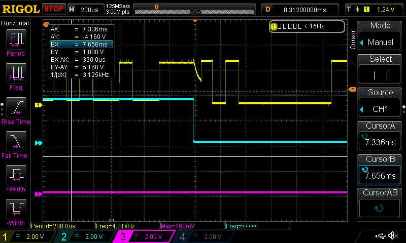
    On scope I see following when TX is done and we start RX:

    Can this small glitch cause an issue? It's when DE/RE goes down. Also data on RS485 looks OK but what I receive on RX pin is what was posted above. Any idea what to check or adjust? How does signal should look like when TX is finished and we start RX? Thanks

  • Hi Marek,

    I'm glad to hear you've made progress!

    I agree that an incompatibility between RS-485 transceivers from different manufacturers is a very unlikely explanation.

    Which signals are shown in the capture above.  I believe the blue one is probably DE.  Is the yellow one R?  If so, why would it be toggling during the first part of the capture when DE is high - I thought /RE and DE were controlled by the same line?

    Anyway, the yellow signal looks like something that has been disabled and is therefore decaying in voltage to some steady-state bias point.  This could happen on the R output when /RE is high.  This can be problematic since many serial communications protocols detect the high-to-low transition as signaling the start of a word or frame.  So, in order to avoid falsely detecting this glitch as a start bit the solution is usually to place a pull-up resistance on the "R" output.  Something in the 1 kOhm to 10 kOhm range is suitable.  This keeps the voltage high whenever the output is disabled.

    If the yellow trace is the A or B line, it would be good to look at the differential signal when this happens and compare it to the differential input thresholds of the transceiver.  There could be a similar phenomenon here where a disabled or high-Z state results in something that can be interpreted as a "low" level, and this would be incorrectly interpreted as a start bit.  The solution here would be similar - that is, you would provide some positive differential bias to the receiver input by pulling A high and B low.  (You could read more about this here: https://e2e.ti.com/blogs_/b/industrial_strength/archive/2016/12/06/rs-485-basics-two-ways-to-fail-safe-bias-your-network.)

    Regards,
    Max