This thread has been locked.

If you have a related question, please click the "Ask a related question" button in the top right corner. The newly created question will be automatically linked to this question.

DS90UB960-Q1: DS90UB960-Q1 and DS90UB953-Q1 pair EMI issue

Part Number: DS90UB960-Q1
Other Parts Discussed in Thread: DS90UB954-Q1

Hi all,

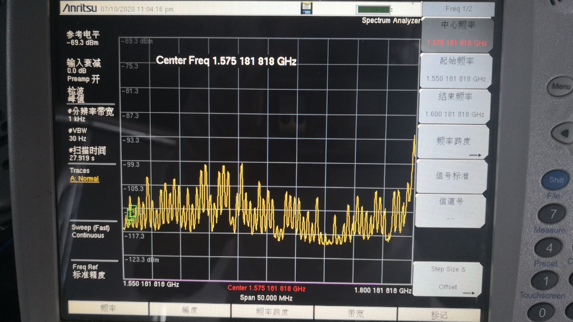
I'm developing FPD Link-III interface automotive cameras with UB960 and UB953 pair. However, I met EMI issue when using our system with other RF type modules, such as GPS. It interfers the GPS signal severely when the GPS antenna is close to the Coax cable during video streaming. I have two questions about this issue:

1. I checked UB960 datasheet, and found that Spread-Spectrum Clocking (SSC) option can be applied to mitigate EMI. But, how to using this SSC feature on UB960? 

2. I switched UB960 external REFCLK to internal REFCLK (both 25MHz), the EMI level seemed to be much lower, but the video stream turned to be incomplete. With internal REFCLK(25MHz), I recieved only about 1/3 active image data per frame. So, what's the matter?

BTW, some other information may be useful. The UB960 is working in CSI-2 synchronization mode with external REFCLK=25MHz. The video stream is 1.7Mpx/40fps or 1.7Mpx/25fps.

Looking forward to advices and guidances. Thanks very much.

Sincerely,

Steve Pan

  • Hello Steve,

    To utilize SSC for 953->960, you must change the 960's 25MHz REFCLK input to a 25MHz REFCLK input with SSC and the link must be operated in synchronous mode. This can be generated by a clock generator device or an oscillator with fixed SSC output. The spreading deviation and modulation frequency limits are described in the datasheet.

    Changing the 960 to internal clock mode is not a supported feature so it is difficult to say what could be causing the issues you saw there. 

    Best Regards,

    Casey 

  • Hello Casey,

    Thank you very much for answering my questions. Your reply is very useful for me to understand the problem I meet.

    May I ask some more questions:

    1. I measured the RE spectrum, as shown below in the figure. I see many peaks in the plot that ranges from about 1GHz to 2GHz. (Frequeces above 2GHz are not checked and thus not specified in the test.) The energy of the RE does neither congregate around the foward channel rate, nor around the back channel rate. How can it be like this? The situation looks much more complicated than what I expected.

    2. The RE energy is at a high level all along the entire Coax cable. What's the matter? Does it say that the cable leaks? Or the problem is a common-mode EMI problem? Can it be better if I put a common mode filter close to each FPD3 input pair of UB960?

    3. I use 12V PoC in my system. The EMI level degrades a little when I change the power level to 8V. However, when I disable the PoC function, the level of the RE energy is as high as that with PoC enabled. Can you give me some guidances about the PoC usage for low EMI application?

    Regards,

    Steve Pan

  • Hello Steve,

    can you measure the frequency of these peacks? i.e. every how many KHz/MHz they are happening? This could be a resonance from the power supply for example.

    Also can you tell me if the Camera is Grounded/ ECU is grounded or not?

  • Hello Hamzeh,

    Thanks for replying me.

    I measured the interval of the frequency peaks. It is about 750kHz. But there is not any frequency in this scale in my system. There are a few DCDC bucks in our deserializer board, with switching frequencies as 501kHz, 1MHz, 2.4MHz, and 2.5MHz. If it were caused by a resonance from power, but how can the frequency peaks repeat with 750kHz intervals?

    The camera and the ECU are all grounded to the negative pole of the battery. The ground net is connected to the shield of the vehicle.

    BTW, the frequency peaks can only be measured when the video stream is on.

    Regards,

    Steve Pan

  • Hello Steve,

    System level EMI and EMC are very dependent on PCB design, connector cable, shielding and grounding techniques.
    For mitigation without changing PCB structure you can adjust DS90UB954-Q1 REFCLK frequency to 24 MHz or 26 MHz to shift any frequency related spectrum. Alternately you can apply SSC at REFCLK input of 25 MHz +/- 0.5%. This will introduce spread spectrum on back channel and forward channel.