This thread has been locked.

If you have a related question, please click the "Ask a related question" button in the top right corner. The newly created question will be automatically linked to this question.

DP83867CR: Link up does not work properly at 1000/100Mbps.

Part Number: DP83867CR


The following problems have occurred in the board under development using DP83867CRRGZT.

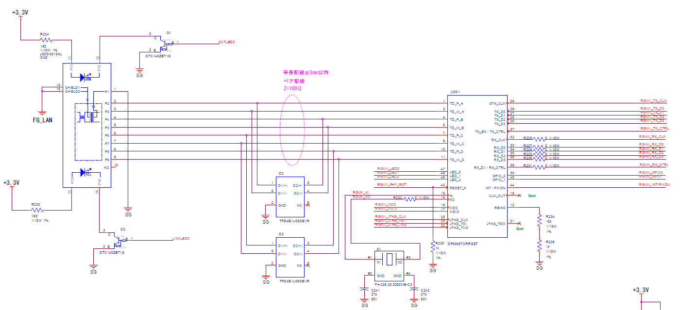
There is no setting from MDIO, and it is launched only by Strap Configuration.
The settings related to 1000BASE-T in the Strap Configuration are as follows.

-RX_DV/RX_CTRL:Mode3(Autonego Enable)
-LED1:Mode1(advertise ability of 10/100/1000)

Case 1
With 1000Mbps Autonegotiation Enable, it links with the terminal (PC) but not with the HUB.
When the Master/Slave setting was changed to fixed Master, it linked with PC/HUB.
On the other hand, if you fixed it to Slave, it will not link to either HUB/PC.

Case 2
If set to 1000Mpbs Full-Duplex fixed, neither PC nor HUB will be linked.

Case 3
When connecting to a HUB/PC with 100M Autonego setting, the HUB/PC repeats Link Up/Down.
At that time, DP83867CR is not always linked.

  • Hello Kohei,

    Can you provide the strap settings you are implementing in each case described above? Do you have the ability to read/write through MDIO to the PHY?

    Regards,
    Justin 

  • Hello Justin,

    The settings for Strap Configuration are as follows for all Cases.

    -RX_D0/D2:Mode1(PHY Addr: 0000)
    -RX_DV/RX_CTRL:Mode3(Autonego Enable)
    -LED_1/2:Mode1(RGMII Clock Skew TX[2:0]:000(2ns), ANEG_SEL:0(advertise ability of 10/100/1000))
    -LED_0:Mode1(Mirror Disable)
    -GPIO_0/1:Mode1(RGMII Clock Skew RX[2:0]:000(2ns))


    MDIO can be controlled from FPGA.
    The result of the dump is shown below.
    (Addr:0x0000-0x0135, data sheet description)

    Addr : Data

    0000 : 1140  0001 : 7949  0002 : 2000  0003 : A231  0004 : 0DE1
    0005 : C5E1  0006 : 006F  0007 : 2001  0008 : 4D58  0009 : 0300
    000A : 0800  000D : 401F  000E : 0000  000F : 3000  0010 : 5048
    0011 : 1002  0012 : 0000  0013 : 90C0  0014 : 29C7  0015 : 0000
    0016 : 0000  0017 : 0040  0018 : 6150  0019 : 4444  001A : 0002
    001E : 0002  001F : 0000  0025 : 0400  002D : 0000  0031 : 1030
    0032 : 00D3  0033 : 0000  0043 : 07A0  0055 : 0000  006E : 0000
    006F : 0100  0071 : 0000  0072 : 0000  0086 : 0068  00E9 : 9F22
    00FE : E721  0134 : 1000  0135 : 0000


    The following settings were made using MDIO from FPGA.

    -Addr:0x0004
       bit11(ASM_DIR):1
       bit10(PAUSE):1

    -Addr:0x0031
       bit7(RESERVED):0
       *Xilinx AR# 70686 Workaround (just in case)
        URL:japan.xilinx.com/.../70686.html

    -Addr:0x0086
       bit[7:4](RGMII_TX_DELAY_CTRL):0x6(1.75ns)
       bit[3:0](RGMII_RX_DELAY_CTRL):0x8(2.25ns)

    Regards,
    Kohei

  • Hi Kohei,

    Thank you for the register and strap information. I will review the data and respond back in 2-3 days.

    Regards,
    Justin 

  • Hi Kohei,

    Do you issue a software restart after writing register 0x0031[7]=0? Please try this and let me know if it helps your cases.

    Regards,
    Justin 

  • Hello Justin,

    Does software restart mean SW_RESTART of DP83867?
    Or does it mean a software restart on the FPGA side?
    Of course, the software on the FPGA side is not restarted.
    Also, we do not do SW_RESTART of DP83867.

    As a trial, I have set various Reset Registers of DP83867 as follows and confirmed the operation.

    1) Addr:0x0031 bit14(SW_RESTART)=1 write

    -> The phenomenon did not change.
       The value of DP83867 Register did not change because of SW_RESTART.

    2) Addr:0x0031 bit15(SW_RESET)=1 write

    -> The phenomenon did not change.
       The DP83867 Register has returned to the default value due to SW_RESET.

    3) Addr:0x0000 bit15(RESET)=1 write

    -> The phenomenon did not change.
       The value of DP83867 Register did not change due to RESET.

    4) Addr:0x0000 bit11(POWER DOWN)=1 write, then 0 write
       (After setting Power Down, power up again)

    -> The phenomenon did not change.
       The value of DP83867 Register did not change due to POWER DOWN.

    5) Addr:0x0010 bit7(DEEP_POWER_DOWN_EN)=1 write,
       Addr:0x0000 bit11(POWER DOWN)=1 write, then 0 write
       (After setting Deep Power Down, power up again)

    -> The phenomenon did not change.
       The value of DP83867 Register did not change due to POWER DOWN.

    6) Addr:0x0010 bit2(STANDBY_MODE)=1 write, then 0 write
       (After setting Standby, restore it again)

    -> The phenomenon did not change.
       The value of DP83867 Register did not change because of STANDBY_MODE.

    Regards,
    Kohei

  • Hi Kohei,

    Can you confirm that after the SW_Restart none of  Case 1, Case 2, and Case 3 behavior changed? 

    When in Case 1, can you try disabling advertisement of 10M/100M capabilities on both PC/Hub and DP83867? 

    In Case 2, is the DP83867 tried in both Master and Slave modes? 

    Regards,

    Justin 

  • Hello Justin,

    Sorry.
    The register address of SW_RESET and SW_RESTART was typo.
    The contents implemented are not incorrect.

    1) Addr:0x0031 bit14(SW_RESTART)=1 write (wrong)
      ->Addr:0x001F bit14(SW_RESTART)=1 write (correct)

    2) Addr:0x0031 bit15(SW_RESET)=1 write (wrong)
      ->Addr:0x001F bit15(SW_RESET)=1 write (correct)


    - Can you confirm that after the SW_Restart none of Case 1, Case 2, and Case 3 behavior changed?

      -> Yes. There was no change in behavior in Cases 1, 2 and 3.


    - When in Case 1, can you try disabling advertisement of 10M/100M capabilities on both PC/Hub and DP83867?

      ->Sorry. HUB settings cannot be changed, so only DP83867 has been changed.
        There was no change in behavior.

    - In Case 2, is the DP83867 tried in both Master and Slave modes?

      -> Master/Slave fixed setting did not change the behavior.

    Regards,
    Kohei

  • Hello Justin,

    How are you considering this question?
    If you have any other information that we need to confirm, please let us know.

    Regards,
    Kohei

  • Hello Justin,

    I haven't received a response since I presented the survey information on Jul 20, 2020.
    Is there a current survey status and answers?

    Regards,
    Kohei

  • Hello Kohei,

    I apologize for the delay. Can you please provide the schematic of the DP83867 for this application? In the register data provided above, register 0x0001[5] is [0], showing Auto-negotiation is not complete. Can you let me know if this is present in cases where the device will not link in 1000Mbps or 100Mbps mode?

    Regards,

    Justin 

  • Hello Justin,

    Thank you for your reply.

    The circuit diagram around the DP83867CR is attached.
    As part of Autonego's Strap Configuration, I also checked the Pullup/down resistance value of RX_CTRL, but it seems that there is no particular problem.
    (Pullup:5.76kohm, Pulldown:2.49kohm)

    The receiving FPGA side does not set the internal pull-up/down resistance.

    If you have any questions, please contact us.

    When neither 1000M/100M is linked, 0x0001[5]=0 and Autonego has not been completed.

    Regards,
    Kohei

  • Hi Kohei,

    Can you try an experiment to rule out the Xilinx AR# 70686 Workaround? Please try this in cases 1 and 3. 

    Please DNP RX_CTRL pull-up strap resistor (R247). Then include the register writes to clear the bit in register 0x0031.

    Steps:

    • strap RX_CTRL to mode 1 through pull-down resistor
    • Write register 0x0031[7]=0
    • Perform software restart through register 0x001F=4000

    Case 2 that you described above is not a valid configuration as auto-negotiation must always be enabled for 1000Mbps operation. 

    Regards,

    Justin 

  • Hello Justin,

    1) Can you try an experiment to rule out the Xilinx AR# 70686 Workaround? Please try this in cases 1 and 3.

    I disabled the control of AR#70686, but there was no difference in the phenomenon with Case 1/3.

    2) Please DNP RX_CTRL pull-up strap resistor (R247). Then include the register writes to clear the bit in register 0x0031.

    This experiment changes to Mode 1 (N/A) by not mounting the RX_CTRL pull-up strap resistor (R247), and by applying AR#70686, we are trying to see if there is an improvement in the phenomenon. Is it?
    Is this intended to be a complete reproduction of the defects and measures that required AR#70686?

    I tried it, but again there was no difference in the phenomenon.

    Regards,
    Kohei

  • Hello Kohei, 

    Your description of the experiment is correct. By recreating the RX_CTRL strap in mode 1 and issuing the work-around, we can rule that out as causing the issue. Can you also try auto-negotiation without modifying bits 0x0004[11:10]? 

    Can you provide the partner number information about the HUB that is being used? I would like to investigate this in our lab by recreating the HUB auto-negotiation settings of the HUB or using the HUB you are experiencing this issue on.

    Regards,
    Justin 

  • Hello Justin,

    Sorry for the late reply.

    The HUB we are using is the HP ProCurve Switch 1400-8G J9077A.

    As an additional test, I had Xilinx ZCU104, so I linked it without any problems when I connected it to a HUB.
    However, we have not verified what PHY register settings are made in the FPGA in the ZCU104.

    > Can you also try auto-negotiation without modifying bits 0x0004[11:10]?

    We are currently confirming this matter, so we will reply later.

    Regards,
    Kohei

  • Hi Kohei,

    Please let me know the results of the auto-negotiation tests and read the registers of the Xilinx ZCU104 DP83867? I will review the schematic for that board and compare to your application. I will need time to review and expect to have feedback in 3-4 days. 

    Regards,
    Justin 

  • Hello Justin,

    When I rechecked the circuit diagram, it was found that the circuit of the crystal oscillator used as the master clock of GPHY was incorrect as shown in the figure below.

    Originally, I was planning to connect a capacitor that will be a load capacitance between SGs near the clock input / output section (# 1, # 3) of X1, but I mistakenly put a capacitor between SGs at the GND terminals (# 2, # 4). I had attached it.

    Therefore, when I modified the board so that a capacitor was attached near the clock input / output section (# 1, # 3) and checked it, the operation of both Case 1 and Case 3 improved, and it became possible to link without problems.

    If the load capacitance is not normally set on the crystal unit, the deviation of the output clock will be affected, but this may cause a problem such as this problem that GPHY cannot link under specific conditions. do you have?

    Please check the above contents.

    Regards,
    Kohei

  • Hello Kohei,

    I'm sorry for the delay. Yes, the crystal oscillator and RBIAS resistor are two critical components in ensuring the device will function properly, particularly in 1G mode because the timing margins are tighter at the higher frequencies. The PHY will still access MDC/MDIO and link under some conditions but when deriving the clock to establish link, the loading on the crystal is important to be tuned correctly.

    Regards,
    Justin 

  • Hello Justin,

    Thank you for your reply.

    Please tell me what kind of effect is expected on the behavior of the PHY if the recommended external load capacitor of the crystal unit is not attached like this time.

    1) What kind of problems may occur with 1000/100 / 10Mbps Link?
    2) Is there a possibility that an event such as linking with HUB will occur only when Master Mode is fixed?
    3) Is there a possibility that the device (PC / HUB, etc.) facing the PHY may or may not link?
    4) Is there a possibility that RGMII communication will be affected?
    5) Is there a possibility that MDIO communication will be affected?

    Thank you for your confirmation.

    Regards,
    Kohei

  • Hi Kohei,

    If the crystal oscillator is not properly configured it will affect the PHYs ability to link over the MDI with a link partner. The severity of the issues depends on the variation of the 25MHz input signal. It can range from failing compliance tests to not being able to establish link if the clock is distorted severely. 

    RGMII communication can be affected by the XI pin input but MDIO will not. 

    Regards,
    Justin