Hi Team,
We face the same issue as the below link in TIe2e.(https://e2e.ti.com/support/interface/f/138/t/793067?tisearch=e2e-sitesearch&keymatch=DS90UB936%20GPIO3)
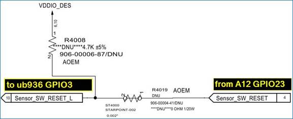
We set the GPIO3/INTB being the input port and CPU will provide the high and low signal to GPIO3/INTB. In CPU side, we could select the drive current to be 2mA/4mA/8mA.
As you see in below waveform, white is successful low to high transition and yellow is failed low to high transition. If we set drive current = 2mA, the low to high transition is seldom failed. If we select larger drive current, the failed rate will become bigger.
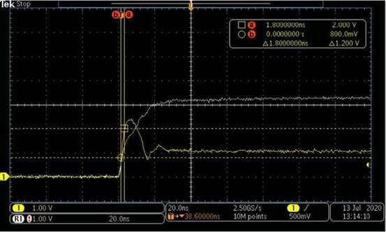
We also change to use GPIO0/1/2/4/5/6, they are fine to use higher drive current. So we think the root cause is the multi-function of GPIO3.
Could you let me know the limitation of using GPIO3 like low to high slew rate or ......? Also let me know why higher drive current fail the transition.
PS. We also try to add the pull-up resistor(4.7k) to VDD(3.3V). the failed transition still occur. failed low to high transition. If we set drive current = 2mA, the low to high transition is seldom failed. If we select larger drive current, the failed rate will become bigger.

We also change to use GPIO0/1/2/4/5/6, they are fine to use higher drive current. So we think the root cause is the multi-function of GPIO3.
Could you let me know the limitation of using GPIO3 like low to high slew rate or ......? Also let me know why higher drive current fail the transition.
PS. We also try to add the pull-up resistor(4.7k) to VDD(3.3V). the failed transition still occur.
Regards,
Roy