This thread has been locked.

If you have a related question, please click the "Ask a related question" button in the top right corner. The newly created question will be automatically linked to this question.

DS90UB960-Q1: 960 + 953 + 4*external FrameSync sensor unable to display normally

Part Number: DS90UB960-Q1

hi teams

"e2e.ti.com/.../921939"

This is the question I submitted before. I used the internal trigger sensor. The problem has been solved, and 4 cameras can be turned on at the same time, and preview normally.

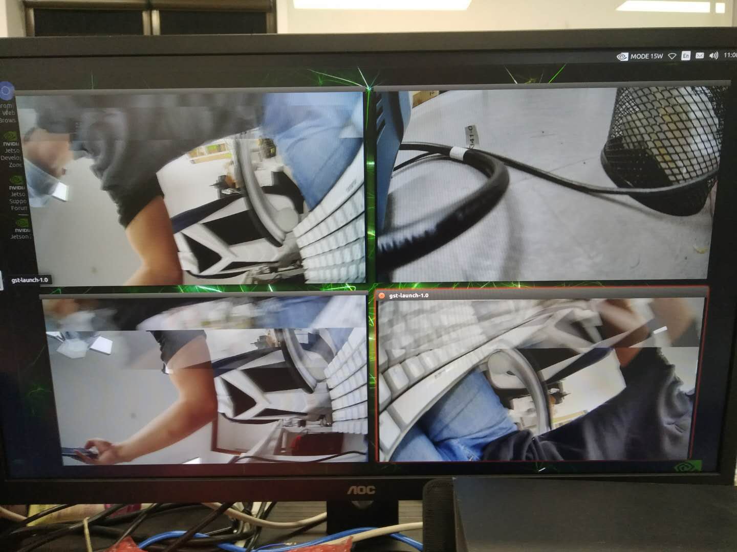
Now I have replaced it with the external trigger camera.  I use the internally generated framesync mode to provide framesync signals to the sensors,The following is the configuration of the register. And the display effect is shown in the picture.

There are three camera images that can be previewed in real time, but the images are misplaced, as shown in the picture. The other one camera only shows one image and cannot be previewed in real time

Is this a problem with sensor or 960 or 953 configuration?

Looking forward to your reply, Thanks very much.

#960 reg config
i2cset -f -y 8 0x3d 0x4c 0x01
i2cset -f -y 8 0x3d 0x58 0x5e
i2cset -f -y 8 0x3d 0x5c 0x30
i2cset -f -y 8 0x3d 0x5d 0xda
i2cset -f -y 8 0x3d 0x65 0xba
i2cset -f -y 8 0x3d 0xb0 0x1c
i2cset -f -y 8 0x3d 0x70 0x1e
i2cset -f -y 8 0x3d 0x72 0x00
i2cset -f -y 8 0x3d 0x6e 0xAA
i2cset -f -y 8 0x3d 0x6F 0xAA
sleep 0.5
i2cset -f -y 8 0x3d 0x4c 0x12
i2cset -f -y 8 0x3d 0x58 0x5e
i2cset -f -y 8 0x3d 0x5c 0x32
i2cset -f -y 8 0x3d 0x5d 0xda
i2cset -f -y 8 0x3d 0x65 0xbc
i2cset -f -y 8 0x3d 0xb0 0x1c
i2cset -f -y 8 0x3d 0x70 0x5e
i2cset -f -y 8 0x3d 0x72 0x55
i2cset -f -y 8 0x3d 0x6e 0xAA
i2cset -f -y 8 0x3d 0x6F 0xAA
sleep 0.5
i2cset -f -y 8 0x3d 0x4c 0x24
i2cset -f -y 8 0x3d 0x58 0x5e
i2cset -f -y 8 0x3d 0x5c 0x40
i2cset -f -y 8 0x3d 0x5d 0xda
i2cset -f -y 8 0x3d 0x65 0xbe
i2cset -f -y 8 0x3d 0xb0 0x1c
i2cset -f -y 8 0x3d 0x70 0x9e
i2cset -f -y 8 0x3d 0x72 0xAA
i2cset -f -y 8 0x3d 0x6e 0xAA
i2cset -f -y 8 0x3d 0x6F 0xAA
sleep 0.5
i2cset -f -y 8 0x3d 0x4c 0x38
i2cset -f -y 8 0x3d 0x58 0x5e
i2cset -f -y 8 0x3d 0x5c 0x42
i2cset -f -y 8 0x3d 0x5d 0xda
i2cset -f -y 8 0x3d 0x65 0xc0
i2cset -f -y 8 0x3d 0xb0 0x1c
i2cset -f -y 8 0x3d 0x70 0xde
i2cset -f -y 8 0x3d 0x72 0xFF
i2cset -f -y 8 0x3d 0x6e 0xAA
i2cset -f -y 8 0x3d 0x6F 0xAA
sleep 0.2

i2cset -f -y 8 0x3d 0x10 0x91
i2cset -f -y 8 0x3d 0x19 0x0A
i2cset -f -y 8 0x3d 0x1A 0xD7
i2cset -f -y 8 0x3d 0x1B 0xBA
i2cset -f -y 8 0x3d 0x1C 0x71
i2cset -f -y 8 0x3d 0x18 0x01
i2cset -f -y 8 0x3d 0x1f 0x00
i2cset -f -y 8 0x3d 0x32 0x01
i2cset -f -y 8 0x3d 0x33 0x03
i2cset -f -y 8 0x3d 0x32 0x13
i2cset -f -y 8 0x3d 0x33 0x03
i2cset -f -y 8 0x3d 0x20 0xFC
i2cset -f -y 8 0x3d 0x20 0x0C
# 953 reg config
i2cset -f -y 8 0x18 0x02 0x73
i2cset -f -y 8 0x18 0x0e 0x1e
i2cset -f -y 8 0x18 0x0d 0xe1
i2cset -f -y 8 0x19 0x02 0x73
i2cset -f -y 8 0x19 0x0e 0x1e
i2cset -f -y 8 0x19 0x0d 0xe1
i2cset -f -y 8 0x20 0x02 0x73
i2cset -f -y 8 0x20 0x0e 0x1e
i2cset -f -y 8 0x20 0x0d 0xe1
i2cset -f -y 8 0x21 0x02 0x73
i2cset -f -y 8 0x21 0x0e 0x1e
i2cset -f -y 8 0x21 0x0d 0xe1

  • Does anyone have a similar problem? How to solve the problem ?

  • Hi Xiangbo, 

    Looking at your script, you need to have GPIO0 disabled as an output, and instead have it enabled as an input. You can send you external frame sync to GPIO0. 
    Then you need to change 0x18 [7:4] = 1000 and [0] = 0 to turn on FS generation and enable FS from external GPIO0. 

    THanks, 

    Sally 

  • HI Sally

    Thanks for your reply.

    Does gpio0 refer to 960's or 953's? If it's   belongs to 960, what kind of signal should be  given to the Gpio0 of 960 , but our hardware design, 960 all gpios are empty

    If the gpio0 belongs to 953, the register 0x0e default value is 0x0f which refer to     gpio0 been set to an input gpio, but there is no stream out before i set the gpio0 be a output type, and in hardware design the gpio should be a output type.

    Thanks.

  • Hi Xiangbo, 

    it refers to the 960. You should send in a square waveform as shown in figure 30 of the d/s. You may also consider using internal frame sync as well. 

    Thanks, 
    Sally 

  • hi Sally,

    The current configuration is using internal frame sync. Because of the hardware design, it is impossible to input square wave signal to 960 gpio0. I want to know if there are still problems in my configuration and why the 4-channel video can not be displayed normally

    thanks very much.

  • Hi Xiangbo, 

    For internal frame sync please see my attachment script. I have made some changes and added comments to your script. 

    #960 reg config
    
    i2cset -f -y 8 0x3d 0x4c 0x01 #RX Port 0 
    i2cset -f -y 8 0x3d 0x58 0x96 #BC 50 Mbps
    i2cset -f -y 8 0x3d 0x5b 0x30 #Ser id
    i2cset -f -y 8 0x3d 0x5c 0xda #slave id 0
    i2cset -f -y 8 0x3d 0x65 0xba #slave alias 0
    i2cset -f -y 8 0x3d 0x72 0x00 #csi-2 , vc-id 0
    i2cset -f -y 8 0x3d 0x6e 0xAA #FS signal to GPIO 0/1 
    
    sleep 0.5
    i2cset -f -y 8 0x3d 0x4c 0x12 #RX Port 1 
    i2cset -f -y 8 0x3d 0x58 0x96 #BC 50 Mbps
    i2cset -f -y 8 0x3d 0x5c 0x32 #Ser alias id
    i2cset -f -y 8 0x3d 0x5d 0xda #slave id 0
    i2cset -f -y 8 0x3d 0x65 0xbc #slave alias 0
    i2cset -f -y 8 0x3d 0x72 0x55 #csi-2 , vc-id 1
    i2cset -f -y 8 0x3d 0x6e 0xAA #FS signal to GPIO 0/1 
    sleep 0.5
    i2cset -f -y 8 0x3d 0x4c 0x24 #RX port 2
    i2cset -f -y 8 0x3d 0x58 0x96 #BC 50 Mbps
    i2cset -f -y 8 0x3d 0x5c 0x40 #Ser alias id
    i2cset -f -y 8 0x3d 0x5d 0xda #slave id 0
    i2cset -f -y 8 0x3d 0x65 0xbe #slave alias 0
    i2cset -f -y 8 0x3d 0x72 0xAA #csi-2 , vc-id 2
    i2cset -f -y 8 0x3d 0x6e 0xAA #FS signal to GPIO 0/1 
    
    sleep 0.5
    i2cset -f -y 8 0x3d 0x4c 0x38 #RX port 3
    i2cset -f -y 8 0x3d 0x58 0x96 #BC 50 Mbps
    i2cset -f -y 8 0x3d 0x5c 0x42 #Ser alias id
    i2cset -f -y 8 0x3d 0x5d 0xda #slave id 0
    i2cset -f -y 8 0x3d 0x65 0xc0 #slave alias 0
    i2cset -f -y 8 0x3d 0x72 0xFF #csi-2 , vc-id 3
    i2cset -f -y 8 0x3d 0x6e 0xAA #FS signal to GPIO 0/1
    
    sleep 0.2
    
    i2cset -f -y 8 0x3d 0x10 0x91 # frame sync signal, device status, enabled
    i2cset -f -y 8 0x3d 0x19 0x36 # FS high time MSB
    i2cset -f -y 8 0x3d 0x1A 0x41 # FS high time LSB
    i2cset -f -y 8 0x3d 0x1B 0x36 # FS low time MSB
    i2cset -f -y 8 0x3d 0x1C 0x41 # FS low time LSB
    i2cset -f -y 8 0x3d 0x18 0x01 #enable FS
    i2cset -f -y 8 0x3d 0x1f 0x00 #1.6 Gbps CSI-2 TX data rate
    i2cset -f -y 8 0x3d 0x32 0x01 #CSI0 select
    i2cset -f -y 8 0x3d 0x33 0x03 #CSI enabled and 4 lanes
    i2cset -f -y 8 0x3d 0x32 0x13 #CSI0&1 select. CSI1 read register
    i2cset -f -y 8 0x3d 0x33 0x03 #CSI enabled and 4 lanes
    #i2cset -f -y 8 0x3d 0x20 0xFC #forwarding disabled for RX0-3, map RX0&1 to CSI-2 Port 0. map RX0&1 to CSI-2 port1
    #i2cset -f -y 8 0x3d 0x21 0x03 #RR forwarding disabled
    #i2cset -f -y 8 0x3d 0x20 0x0C #forwarding enabled for RX0-3, map RX0&1 to CSI-2 Port 0. map RX0&1 to CSI-2 port1
    #i2cset -f -y 8 0x3d 0x21 0x17 #RR forwarding disabled, basic sync forwarding
    
    
    # 953 reg config
    i2cset -f -y 8 0x18 0x02 0x73 #CSI continuous clk, 4 lane, 1.8 I2c
    i2cset -f -y 8 0x18 0x0e 0xf0 #GPIO0 input disabled, output enabled. 
    i2cset -f -y 8 0x18 0x0d 0x1c #enable remote GPIO1-3, write 1 on GPIO0
    i2cset -f -y 8 0x19 0x02 0x73
    i2cset -f -y 8 0x19 0x0e 0xf0
    i2cset -f -y 8 0x19 0x0d 0x1c
    i2cset -f -y 8 0x20 0x02 0x73
    i2cset -f -y 8 0x20 0x0e 0xf0
    i2cset -f -y 8 0x20 0x0d 0x1c
    i2cset -f -y 8 0x21 0x02 0x73
    i2cset -f -y 8 0x21 0x0e 0xf0
    i2cset -f -y 8 0x21 0x0d 0x1c

  • Hi Sally.

    We tried the External FrameSync Control by taking 960 gpio4 out by welding wires, and sending in a square waveform.the frequency of the square waveform is 30Hz, and the duty cycle is 50%. The external signal can be transfor to 953 and been output through the GPIO0 of 953. On the pin of 953 GPIO0,The signal can be measured through an oscilloscope.We can get video stream by gst command, But the stream is also abnormal, As show in the video. I turn round the camera body's angle, 0, 90, 270, 360 degree,No matter which angle, the top of the screen is always abnormal. I only connected one camera, Before I still think this is  a proble of bandwidth, while I change the square waveform frequency to 1.8Hz, the problem is alse exist. Now i think this is not a problem of bandwidth, And I had configure the CSI-2 Output Lane Speed to 1.6Gbps.What's the problem?

  • Hi Xiangbo, 

    In this video, you only have on camera connected? In your previous photo, you did not show this issue. Have you changed any other configurations besides external frame sync? 

    Thanks, 

    Sally 

  • Could you try running the script I sent you before? I just want to make sure we can work through this together, step by step. Let's get all the cameras running with internal frame sync and make sure there is no issue. Then I can send you a new script to transition to external frame sync. 

  • Hi Sally

    I only connect one camera on my board.


    In previous i didn't describe the problem clearly. In my previous photo, The phenomenon of the problem is the same.And there was no video file provided previously, so it's not easy to Distinguish it.


    This problem occurred after the external trigger camera was replaced.I thought it was also caused by the bandwidth problem, but now I find that this problem also exists when only one camera is connected.


     I tried External FrameSync Control and Internally Generated FrameSync, But now whether Internally Generated FrameSync or External FrameSync Control the problem is exist.


    In Internally Generated FrameSync mode, Whether your script or mine the problem is remained, The GPIO0 of 953 is constant value of 1 which I throuth should be a square waveform.

    Thanks.

  • Hi Xiangbo, 

    Ok, so GPIO's are not being programmed correctly on either SER/DES side.

    1. On the DES, program 0x4C = 0x01 #select RX0

    2. On the DES, read 0x5C #SER_ALIAS0

    3. On the DES, use scripting tab and do a remote read. board.ReadI2C(SER_ALIAS0, 0x00). #use the value read from 0x5C as the register address

    4. On the DES, use the scripting tab and do a remote write. board.WriteI2C(0x0E, 0xF0) #Enable remote deserializer GPIO data on local GPIO

    4. On the DES, use the scripting tab and do a remote write. board.WriteI2C(0x0D, 0x1C) # Enable GPIO0 ouput

    Then probe and let me know if you see the frame sync signal on the SER.