This thread has been locked.

If you have a related question, please click the "Ask a related question" button in the top right corner. The newly created question will be automatically linked to this question.

DP83826I: Development Board

Part Number: DP83826I

Hi,

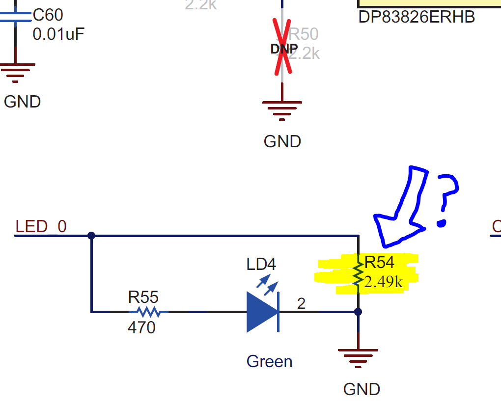
Just wanted to know why the highlighted resistor is placed in parallel across the resistor-LED on the DP83826I development board?

Best,

~Alicia

  • Hi Alicia,

    This resistor works as the pull-down resistor to set the LED_0 bootstrap. This way the LED_0 pin is strapped "low" and the LED_0 pin will be configured to an Active High mode. 

    Regards,

    Justin 

  • Hi Justin,

    I cannot find any documentation that would have told me that there are bootstraps to define active high or low for this output - so I am concerned there might be more that I am missing about how to best apply the DP83826I from Texas Instruments.

    Could you please direct me to this documentation?

    Also, this circuit board is constrained for footprint space. It appears the LED active high / active low can be configured by MDIO from host microcontroller, but I am not sure.

    Thanks,

    ~Alicia 

  • Hi Alicia,

    The DP83826I datasheet does not explicitly state that LED pins will be configured into active high or active low mode, that is a good note to highlight in a datasheet refresh. 

    The LED will be in the active state opposite of the bootstrap setting. If the LED is strapped with a PU resistor, the LED will be active low, and if the LED is strapped with a PD resistor, the LED will be active high. This is also controllable through register configuration as you mentioned. 

    Regards,
    Justin