This thread has been locked.

If you have a related question, please click the "Ask a related question" button in the top right corner. The newly created question will be automatically linked to this question.

TUSB1064: DP Linktraining in 2Lane fails

Part Number: TUSB1064


Hello team,

In the case of the following settings, DP Linktraining in 2Lane fails.
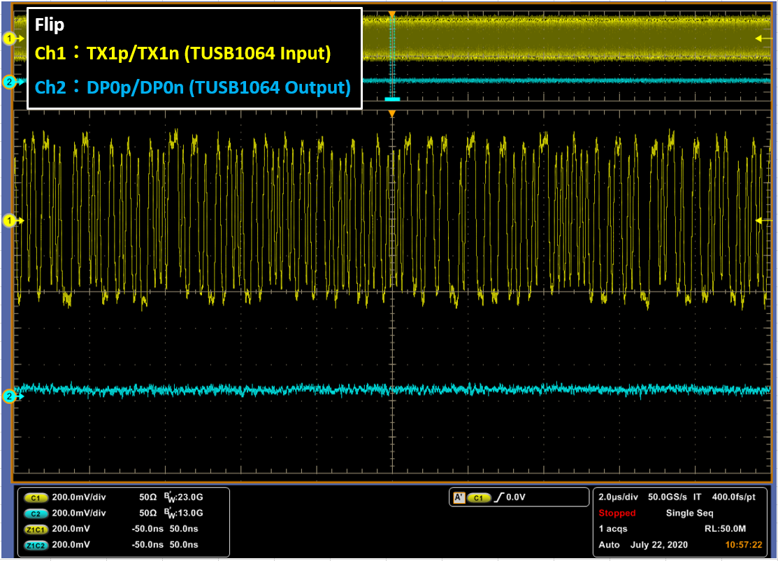
・NG1

 4 Lane DP – With Flip 

  CTL1:High
  CTL0:Low
  FLIP:High

 0x13 = 0x00 (AUX snoop enabled.)

・NG2

 4 Lane DP – With Flip 

  CTL1:High
  CTL0:Low
  FLIP:High

 0x13 = 0x8C (AUX snoop disabled. DP Lane 2,3 Disabled. )

Also, in the case of the following settings, Linktraining in 2 Lane succeed.
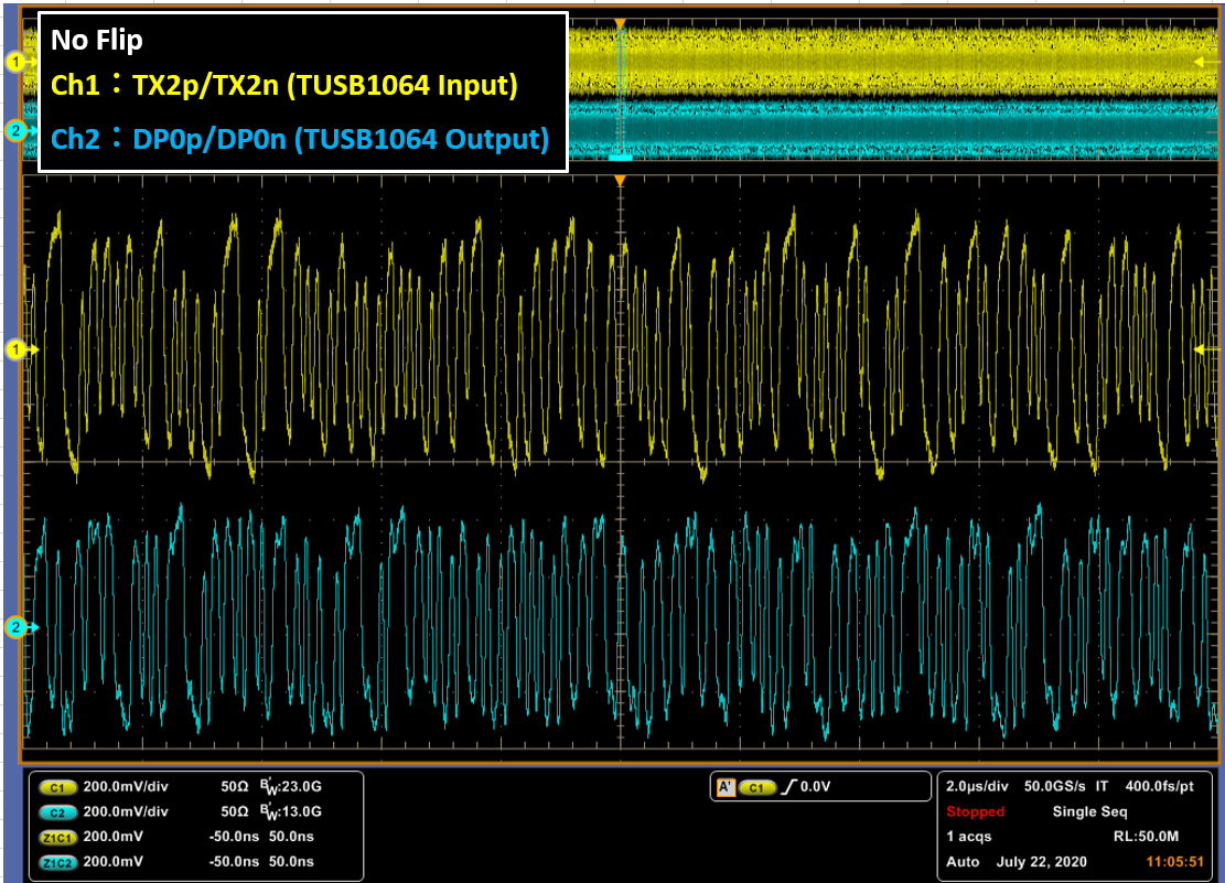
・OK1

 4 Lane DP - No Flip
 CTL1:High
 CTL0:Low
 FLIP:Low

 0x13 = 0x00 (AUX snoop enabled.)

・OK2

 One Port USB 3.1 + 2 Lane DP– With Flip
 CTL1:High
 CTL0:High
 FLIP:High

 0x13 = 0x00 (AUX snoop enabled.)

・OK3

 4 Lane DP – With Flip 

  CTL1:High
  CTL0:Low
  FLIP:High

 0x13 = 0x80 (AUX snoop disabled.)

Why doesn't Linktraining in 2 Lane succeed with the NG case?

  • Hi,

    Is this the correct summary?

    In the failed 2 lane case, does the MAX_LANE_COUNT in the DPCD register being set to 2 as well?

    Thanks
    David

  • Dear David,

    >Is this the correct summary?
    Yes, that's correct.

    > In the failed 2 lane case, does the MAX_LANE_COUNT in the DPCD register being set to 2 as well?
    MAX_LANE_COUNT (00002h) is set to 4 in both OK cases and NG cases.
    Also, LANE_COUNT_SET(00101h) is set to 2 in both OK cases and NG cases.

    Regards,

  • Hi,

    Since the source and sink will only see each other and not knowing the existence of the TUSB1064 between them, you need to make sure the source/sink LANE COUNT in their DPCD registers matches with the TUSB1064 configuration. For example, source (2 lane) + TUSB1064 (2 lane) + sink (2 lane) or source (2 lane) + TUSB1064 (4 lane) + sink (2 lane) would both work. But source (4 lane) + TUSB1064 (2 lane) + sink (4 lane) would not work since the source and the sink expect link training to pass on all 4 lanes. But with the TUSB1064 being configured to enable only 2 lanes(Lane 0 and 1), the 4 lane link training would always fail on lane 2 and 3 unless the source and the sink can downgrade from 4 lanes to 2 lanes. 

    If the LANE configuration is correct, then we need to look for other root causes. If you are using the TUSB1064 SBU/AUX switch, please double check the common mode voltage on the TUSB1064 AUXP/N and SBU1/2 between the passing and the failing case. The common mode voltage must meet the TUSB1064 datasheet requirement for the link training data to pass between the AUX switch.

    Do you have a Type-C analyzer that can capture both USB CC and DP AUX traffic?

    Thanks

    David

  • Dear David,

    I got the AUX and CC data by the analyzer.
    Please confirm it.

    Regards,

    TUSB1064.zip

  • Hi,

    Looking at the AUX log file for both the FLIP and NO_FLIP case, I see the CR_DONE (clock recovery done) is set to 1, so the connection from the Type-C connector to the DP sink is not a problem.

    The difference is that DP EQ training passed with the NO_FLIP case but failed with the FLIP case at both 5.4G and then 2.7G data rate.

    1. What TUSB1064 DP EQ are you setting to?

    2. Why does the DP sink not request any increase in source PRE-EMPHASIS level?

    3. Why is link training able to complete with minimum SWING and PRE-EMPHASIS level in the NO-FLIP case, but require MAX SWING level in the FLIP case? Is there a difference in the TX1/RX1 and TX2/RX2 routing between the Type-C connector and the TUSB1064? 

    Thanks

    David

  • Dear David,

    >Looking at the AUX log file for both the FLIP and NO_FLIP case, I see the CR_DONE (clock recovery done) is set to 1, so the connection from the Type-C connector to the DP sink is not a problem.
    You're right, CR_DONE is set to 1, but when I actually measure the waveform with an oscilloscope, there is no signal output from the TUSB1064.

    >1. What TUSB1064 DP EQ are you setting to?
    I've tried all EQ settings and link training fails on the Flip setting.

    >2. Why does the DP sink not request any increase in source PRE-EMPHASIS level?
    DP sink specifications.

    >3. Why is link training able to complete with minimum SWING and PRE-EMPHASIS level in the NO-FLIP case, but require MAX SWING level in the FLIP case? Is there a difference in the TX1/RX1 and TX2/RX2 routing between the Type-C connector and the TUSB1064? 
    I think it's because there is no signal output from TUSB1064. There is no difference in routing.


    Could you try to see if the same phenomenon occurs with the TUSB1064 EVM?

    Regards,

  • Hi,

    Can I please take a look at your schematic?

    Can you please probe the DP1, DP2, and DP3 output and see if there is any waveform on these outputs? And are you seeing this issue across multiple boards?

    Thanks

    David

  • Dear David,

    >Can I please take a look at your schematic?
    A portion of the schematic is attached.
    TUSB1064_schematic.pdf

    >Can you please probe the DP1, DP2, and DP3 output and see if there is any waveform on these outputs? And are you seeing this issue across multiple boards?
    In the flip case, there is no signal output from DP1, DP2 or DP3.
    These are also confirmed by multiple boards.

    Regards,

  • Hi,

    1, Are you seeing HPD being driven high in the flip case when there is no output on DP0/1/2/3?

    2. If you disable AUX snoop using register 0x13 in the flip case, are you then able to see the output?

    Thanks

    David

  • Dear David,

    >1, Are you seeing HPD being driven high in the flip case when there is no output on DP0/1/2/3?
    Yes.

    >2. If you disable AUX snoop using register 0x13 in the flip case, are you then able to see the output?
    As mentioned at the very beginning,  there is a setting that will not output even if AUX snoop is disabled.

    ・NG
    0x13 = 0x8C (AUX snoop disabled. DP Lane 2,3 Disabled. )

    When any one of the four lanes is disabled, the output is stopped.
    And even with this setting, the output is normal at No Flip.

    ・OK
     0x13 = 0x80 (AUX snoop disabled.)


    Have you tried to see if the same phenomenon occurs with the TUSB1064 EVM?

    Regards,

  • Hi,

    I have not seen this issue on the TUSB1064 EVM.

    In the 2 DP lane FLIP case, can you

    1. Disable AUX snoop by wring 0x80 to register 0x13

    2. Read back register 0x13 and verify the value of 0x80

    3. Probe TX1, RX1, TX2, and RX2 and verify data is only present on TX1 and RX1

    4. Probe DP0, DP1, DP2, and DP3 output and verify data is present on DP0 and DP1, no data on DP2 and DP3

    5. Write 0x88 to register 0x13

    6. Read back and verify the value of 0x88

    7. Probe DP0, DP1, DP2, and DP3 output, we should still see the waveform on DP0 and DP1

    8. If not, please dump out the entire TUSB1064 registers.

    Thanks
    David

  • Dear David,

    Is it possible to borrow the TUSB1064 EVM?
    I would like to check the behavior of the TUSB1064 EVM.

    >1. Disable AUX snoop by wring 0x80 to register 0x13
    OK.

    2. Read back register 0x13 and verify the value of 0x80
    OK.

    3. Probe TX1, RX1, TX2, and RX2 and verify data is only present on TX1 and RX1
    OK.

    4. Probe DP0, DP1, DP2, and DP3 output and verify data is present on DP0 and DP1, no data on DP2 and DP3
    OK. It is output normally.

    5. Write 0x88 to register 0x13
    OK.

    6. Read back and verify the value of 0x88
    OK.

    7. Probe DP0, DP1, DP2, and DP3 output, we should still see the waveform on DP0 and DP1
     There are no outputs from DP0 and DP1.

    8. If not, please dump out the entire TUSB1064 registers.
    Attach a register dump when AUX Snoop is enabled. (30 bytes read from 0x0A)
    TUSB1064_Register dump.xlsx

    Regards,

  • Hi,

    1. Can you send me the register dump after step 7?

    2. Can you send me a scope picture of VCC(Channel 1), HPD(Channel 2), TX1(Channel 3), and DP0 (CHannel 4)?

    3. Would you please contact the TI local FAE and ask him to submit the free EVM request?

    Thanks

    David

  • Dear David,

    >1. Can you send me the register dump after step 7?
    Register dump after step 7 is attached.
    TUSB1064_Register dump2.xlsx

    >2. Can you send me a scope picture of VCC(Channel 1), HPD(Channel 2), TX1(Channel 3), and DP0 (CHannel 4)?
    The scope image is attached.
    TUSB1064_Waveform.xlsx

    >3. Would you please contact the TI local FAE and ask him to submit the free EVM request?
    OK.

    Regards,

  • Hi,

    Thanks for the data. I have not seen this as this is not an expected device behavior. Is it possible that you can send the board to me for debugging as well?

    Thanks

    David

  • Dear David,

    I asked local TI to lend me a TUSB1064 EVM, but they refused.

    We will send you our board and you can tell us where to send it.

    Regards,

  • Hi,

    What you observed is the correct behavior. I would recommend keeping all 4 DP lanes enabled when AUX snoop is disabled.

    Thanks

    David