This thread has been locked.

If you have a related question, please click the "Ask a related question" button in the top right corner. The newly created question will be automatically linked to this question.

Ground connections in isolated RS485 system

I have a system with a control section and appliance, they are connected with an isolated RS485 interface.

Which will be the best way to set up the grounding?

The user controls with a laptop/tablet, with no ground connection to the electricity mains.

The appliance ground is connected to the mains ground, this connects internally to the system 0V.

The distance between the two installations is 10 metres, and the baud rate is 9600 bps. 

The RS485 isolation is achieved with a USB-UART and digital isolator.

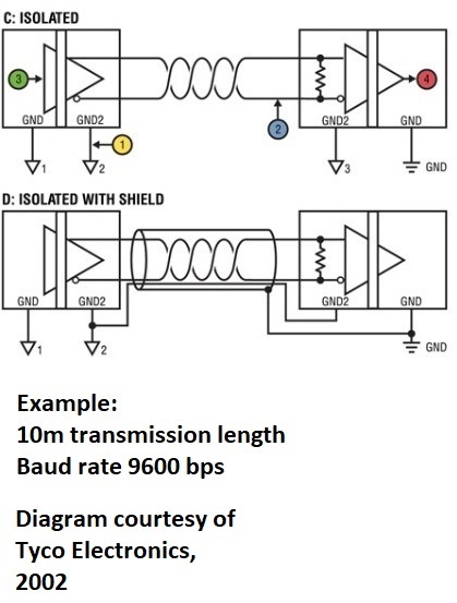
Which system would be best to use, looking at the diagram below, and why? 

Does the screen purely serve to reduce EMC, and also the common ground in the 2nd diagram?

Why is the second option improved with the common ground at all, if the isolation is good, and the RS485 configuration creates a differential switching signal?

Why doesn't the common ground in the 2nd diagram bring in an unwanted potential difference that might raise the common mode voltage to unacceptable levels?

  • Hi Chris,

    This is a good question, thanks for posting it on E2E.

    There are several factors to consider when implementing grounding in an RS-485 interfaced system. 1. Making sure the ground potential difference (GPD) does not exceed a transceiver's common-mode range, 2. managing and reducing ground loop currents, and 3. considering how solutions to these issues impacts electromagnetic compatibility (EMC) are all important during the design process. As with any unique design, the implementation you choose will depend on system characteristics and requirements, but I will describe some common practices and why they are used to address these issues.

    Relying on local earth grounding is not a reliable method of preventing large ground potential differences. Direct connection of remote grounds will prevent such GPDs, but may create a ground loop current path. To prevent this, the RS-485 standard recommends the separation of device grounds and local system grounds using resistors.

    When implementing an isolated RS-485 system, two isolated power supplies can be used to eliminate the ground loop by having the isolated ground connected to the remote ground connection and the non-isolated ground connected to earth.

    Large loops and long runs of cable are susceptible to coupled noise and emit electromagnetic emissions based on the energy traveling through them. By eliminating ground loops, the EMC capabilities of the system also improve. For unavoidable and necessary exceptions, shielded cabling can help reduce the amount of interference on important data lines and more sensitive device supply rails. As the shielding will be absorbing emissions, it is not ideal for use as a remote ground connection. It is best to have a dedicated wire within the protection of the shielding to provide this connection.

    I hope this information helps clarify some of the questions you have regarding the grounding scheme for isolated RS-485. For more info, check out this design guide. Let me know if you have any other questions.

    Regards,
    Eric

  • Thank you Eric, I'll look at your detailed reply today and see what we can do to improve our system.

    Cheers

  • The connections shown in Eric's schematic, do we have to use the ground connection at all if wee are using a differential pair?

    My first question would be though in the Figure 10 example, is regarding the connection point of the shielding. Is this really to the chassis and connection to the 0V some distance from the interface circuit? The diagram shows them in very close connection there. It seems that the shielding is going to conduct EMC right into the transmission 0V

  • Hi Chris,

    Using a ground connection with differential pair signals will help reduce the common mode voltage experienced by the remote node's transceiver. This is a good idea if the nodes will be far apart or are planned to not have reliable grounding (such as if the equipment will be moved or reconfigured by technicians). Because this system will be isolated, the common mode tolerance of the transceiver is very high, but it will still be a good idea to provide a connection to the isolated power ground of the remote node. This will ensure the full tolerance of the transceiver will be used to withstand stresses such as transient events. 

    In regards to the shield connection point, this should be done is a position where it is unlikely to impact the connected system. I believe the figure means to show that the shielding is grounded but not necessarily depict the optimal place where the physical connection should be made. This can be done to a chassis or power ground - ideally something that will be able to tolerate or effectively dissipate any coupled noise. 

    Regards,
    Eric

  • Thanks Eric, I just was picturing the common mode voltage as being more apparent in the isolated system, if the ground line was introduced. 

    I'll keep the issue open further and close it when we've decided more. 

    Thanks for your contributions, very valuable.

  • Hi Chris,

    Glad to hear. I will mark this thread as resolved for now. It will remain unlocked so you can follow up when needed. You may also use the yellow "Ask a related question" button to open a new thread which links to this one.