Other Parts Discussed in Thread: TUSB217
Hi,
For some reasons, we design the circuit of tusb217-q1 as shown in the figure below, that is, the 9th and 10th pins of tusb217-q1 are not connected, and the 5th and 6th pins are respectively connected to DP and DM signal lines.
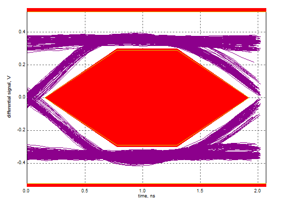
The reason why we do it this way,Because I confirmed that D1M-D2M and D1P-D2P are physically connected through metal wires inside the tusb217-q1.And in this connection method,We have tested the eye diagram which is also OK.
Can tusb217-q1 be used in this way? And I know that there may be some slight differences between the usage method recommended in the datasheet,but is there a greater risk?
Because our product has been designed, if we modify it now, there will be a lot of certification needs to be repeated, which is more troublesome.So please make a detailed evaluation.
thanks!