This thread has been locked.

If you have a related question, please click the "Ask a related question" button in the top right corner. The newly created question will be automatically linked to this question.

TMDS181: TMDS181 Application problems

Part Number: TMDS181

Hi Ti

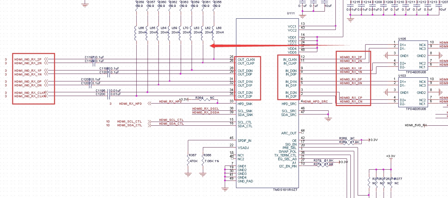
     The HDMI interface chip TMDS181IRGZT was used in our project, but the PCB on the HDMI interface was disconnected during the design.As shown in the figure, we have swapped the data and the clock,

For example, in the IN_CLK channel we took DATa2 from HDMI, and P and N were reversed.Is this working normally?

  • Hi,

    The TMDS181 incorporates swap function, which can set the input lanes in swap mode. The IN_D2 routes to the OUT_CLK position. The IN_D1 swaps with IN_D0. The swap function only changes the input pins.

    The TMDS181 can also swap the input polarity signals. When SWAP/POL is high the n and p pins on each lane will swap. Polarity swap only works when in retimer mode. Take care when this function is enabled and the device is in automatic crossover mode between redriver and retimer modes. When the data rate drops to the redriver level, the polarity swap is lost.

    So the input side looks good if you enable both the lane and the polarity swap (retimer only), but the output connection does not look right in terms of lane and polarity swap.

    Thanks

    David