This thread has been locked.

If you have a related question, please click the "Ask a related question" button in the top right corner. The newly created question will be automatically linked to this question.

SN65HVS880: Need formula or graph to have power dissipation values for different Rlimiting resistor values and Load currents

Part Number: SN65HVS880

How to calculate device power dissipation for different values of  Rlim ?. Worst case power dissipation in data sheet is 2591mW is quite higher. Is there any ways to reduce this by increase Rlim and load currents

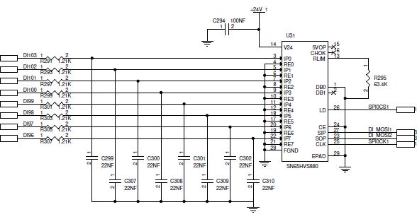
In my circuit, Rlim is 64.2kOhm, limiting the input current to 1.4mA. What would be the power loss of the device in this case ?

  • Hi Gowri,

    Because of the complexity of the part, and all the factors that go into measuring the device, we don't have a publicly available equation to use to calculate max power.

    However I can explain the process to approximate power loss. The major factors in power consumption in this device are input resistance on the input channels, the power dissipation through the Rlim resistor, the load resistance, and finally the supply current. 

    The power loss from Rlim: P_loss_Rlim = (1.25V^2) / R_lim.

    The max power loss at an input pin: P_loss_ipx = (I_Lim * V_ipx(max)) - (V_rex * I_Lim). V_rex is the forward voltage at I_Lim of the LED attached to the REx pin. If this pin is grounded, V_rex = 0V. 

    The regulator can be approximated to the have the following power characteristics: Vin * I_in = V_out * I_out - P_loss; I_out = I_in and P_loss = I_in * (V_in - Vout). Increasing the load resistance can help with the power loss. 

    These equation's won't get you an exact number but it will get you closer to understanding the potential power budget of this part. Higher operating temperatures as well as supply current can also affect the power dissipation. 

    If you can give me the operating temperature, the V24 input voltage, as well as the max input voltage you anticipate on the IPx pins I can see if I can you a closer estimate of power dissipation.

    Best,

    Parker Dodson

  • Hi Parker,

    Thanks for your quick reply and detailed explanation. As requested, I attached draft circuit for your reference. 

    Initial Operating Ambient temperature is 40 Deg C and will increase to 60 Deg C during running condition due to the heat dissipation of other components around it. 

    Please provide us the heat dissipation with the conditions provided.

    Regards,

    Gowri

  • Hi Parker,

    All DI's are connected to 24VDC supply.

    Regards,

    Gowri

  • Hi Gowri,

    Thanks for the detailed follow-up. I can give you an estimated power loss, but there are quite a few non-linear parts so it is more of a ballpark range then an absolute value.

    P_loss_Rlim = 1.25^2 / 63.4k = 24.645 uW 

    P_loss_IPx = (24V - 1.4mA *1.21k) * 1.4mA = 31.228 mW 

    P_loss_supply =  (24 -5) * (Iout + Isupply) = 19 * (8.7mA) =  165.3mW - 8.7mA is worst case supply current with similar set-up to your system

    Approximated Max P_Loss For system = P_loss_Rlim + P_loss_IPx * 8 + P_loss_supply ~ 415.15 mW would be my rough estimation of max power loss. The resistors before the IPx inputs help reduce power loss through the device, as well as the lower current limit. Since you have no load off of the regulator you wont be burning as much power through the regulator, since it isn't terribly efficient. 

    Best Regards,

    Parker Dodson