Part Number: TRS3122EEVM
Hi, guys I'm exploring some Integrated Circuit to use it in an RS232 application, so I found that there exists this Evaluation Kit TRS3122EEVM , and I'd like to understand the connections in the schematic.
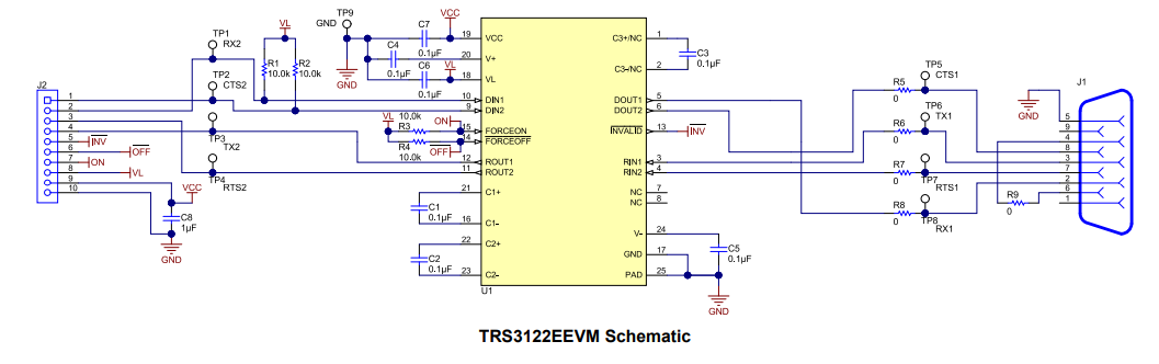
Specifically, in Fig.1. I show the schematic that is showed in pg7 of TRS3122EEVM , and J1 represents the DB9 connector for stablish an RS232 communication. My doubt is: pin 2 (RX pin as per the standard) in J1 is connected to Dout1, but this Dout1 is an output from the U1, and there it is my confussion. So, as long as I understand if a pin is for RX operation, I understand it is used to receive data (so in one device I transmit with TX and at the other device I receive with RX), so in this case RX1 should be connected to a receiver pin of U1 instead of a driver pin of U1. Can someone please explain this to me? what am I missing here?
Thanks
Fig.1. RS232 EVM