This thread has been locked.

If you have a related question, please click the "Ask a related question" button in the top right corner. The newly created question will be automatically linked to this question.

AM26LV31E: Terminations with AM26LV31E and AM26LV32E

Part Number: AM26LV31E
Other Parts Discussed in Thread: AM26LV32E,

Hi Team,

Our customer would like to ask for advice regarding his design with AM26LV31E and AM26LV32E below:


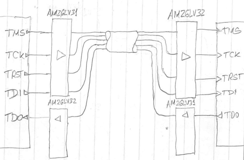
Can you please advise the terminations will need to add to the input of AM26LV31E; the termination in between both AM26LV31E & AM26LV32E, and the termination at the output of AM26LV32E? 

Please let me know if you have any questions with the customer.

Thanks,

Jonathan

  • Hi Jonathan,

    Termination is not required for device functionality but is generally recommended since it can be useful in mitigating transmission line effects (i.e., reflections) when transmitting signals at relatively high speeds over relatively long distances.  For one-way, point-to-point communication like this the termination would typically be placed at the receive end and would use a resistance whose value is equal to the differential characteristic impedance of the cabling used (often 100-120 Ohms).

    Note that the termination resistance does place a load on the driver.  Lower resistances require more output current from the driver and often result in a decrease in output voltage.  The AM26LV31E driver specifies the minimum output voltage with an expected 100 Ohm load to accommodate for termination (this is in line with the RS-422 standard).  Lower resistances would result in lower output levels.

    Best regards,
    Max

  • Hi Max,

    Thank you very much for your support.

    The customer would like to use a 12 pin connector (0.1 spacing, dual row) between AM26LV31E and AM26LV32E? Could be any issues with cross-talk interference?

    Regards,

    Jonathan

  • Jonathan,

    This is a valid concern when higher-speed signals are in close proximity.  If this application always keeps each line's corresponding driver circuit active, though, then I would expect the strength of the signal coming from the driver to be able to overcome the amount of line-to-line coupling that would occur.  If a line's driver becomes disabled and the line becomes high impedance, though, it would be easier for noise to couple on and it would be more likely to have enough crosstalk to result in incorrect receiver output states.

    Of course, this is just an educated guess based on experience.  To find the answer definitively it would be best to either test the hardware or find a way to simulate it (for example, if an s-parameter model of the connector is available).

    Regards,
    Max