This thread has been locked.

If you have a related question, please click the "Ask a related question" button in the top right corner. The newly created question will be automatically linked to this question.

Generic AC or DC input circuit

Other Parts Discussed in Thread: ISO1211

Hi,

I have a requirement to use a single set of Terminal Blocks to process both the AC and DC signals.

Opto-coupler Turn ON Voltage  = 15 VDC, equivalent AC

The input can be either AC or DC, we do not want to turn-on the opto-coupler below 15 VDC = equivalent AC

When AC is used the the AC voltage will not be more than 250 VAC but if it, is it does not matter. We do not need to limit the top voltage.

I was wondering if there is a simple generic circuit that I can use for this space constraints application, thanks in advance.

  • Hi Muhammad,

    Thank you for posting to E2E! TI does not manufacture optocoupler devices, and our isolators do not provide AC signal isolation for voltages this high, hence there is not much assistance we can provide with the circuit you provided above.

    Please let us know if you have additional questions.


    Respectfully,
    Manuel Chavez

  • Hi Muhammad,

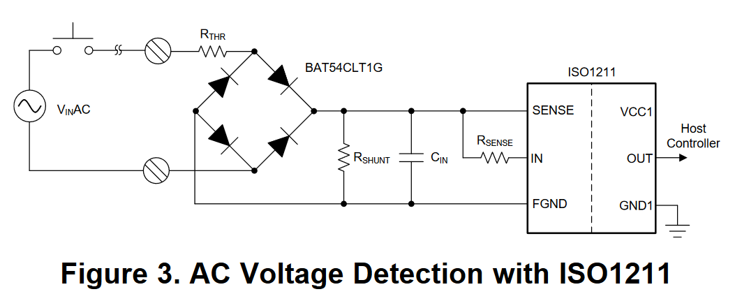
    After discussion with my colleagues, a solution we recommend for this case is using the ISO1211 device to isolate the DC and AC signals as mentioned in this Tech Note (SLLA382A) and similarly to the circuit shown below:


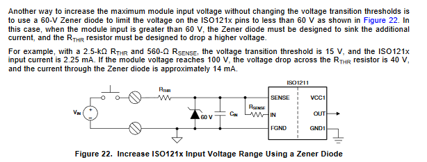
    The front-end component values for a 15V LOW/HIGH threshold can be calculated using our ISO121x Threshold Calculator for 9V to 300V DC and AC Voltage Detection and used for AC and DC operation up to or above 250VAC by adding a 60V Zener clamp as shown in the ISO1211 datasheet and Figure 22 below:


    Please let us know if this is a solution you would like to pursue, and we will provide further assistance!


    Thank you for your time,
    Manuel Chavez

  • Hi Manuel,

    Thanks for this information.

    Please let us know if this is a solution you would like to pursue, and we will provide further assistance!

    Yes, I would like to pursue this solution, this seems like an interesting proposal, let me have a read of the literature, in the meantime if you have any other notes/comments they will be highly appreciated.

  • Hi Muhammad,

    Thanks for letting us know! I will check for any additional notes to share while we await your response.


    Respectfully,
    Manuel Chavez

  • Hi Manuel,

    I have read through the literature and put together the below schematics. According to my quick calculations, when the supply voltage is 250 VAC at J1, the resistor RTHR will have to dissipate 15 W.

    This high wattage resistor is not practical for the application, even adding multiple resistors will not bring the wattage rating to sufficient levels where I can use SMD resistors in the design.

    My understanding is that I have to use 2.5 K resistor (RTHR) in order to ensure transition threshold is 15 V. Please let me have your comments on this, thanks.

  • Muhammad,

    Unfortunately needing 15W of power dissipation for R(THR) seems to be the case. Additionally, the calculator tool that Manuel linked has the suggested R(THR) value of 60k and the inclusion of R(SHUNT) at 15k for a 240V AC system. These values of resistors divide the input voltage down into a range the ISO121x can safely handle. Note that this also brings the threshold voltage up significantly to around 120V.

    Respectfully,

    Lucas